Service Guide
Page 7
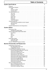
Table of Contents System Specifications 1 Features 1 System Block Diagram 6 UMA 6 Discrete (nVidia 7 Discrete (ATI 8 Your Acer Notebook tour 9 Top View 9 Rear view 10 Left View 11 Right View 12 Base view 13 Indicators 14 Touch Pad Basics 15 Using the ... Keys 18 Hardware Specifications and Configurations 19 System Utilities 31 BIOS Setup Utility 31 Navigating the BIOS Utility 31 Aspire 5742/5742G/5742Z/5742ZG BIOS 32 Information 32 Main 33 Security 34 Boot 37 Exit 38 BIOS Flash Utilities 39 DOS Flash Utility 40 WinFlash Utility 41 Remove HDD/BIOS Password Utilities...
Table of Contents System Specifications 1 Features 1 System Block Diagram 6 UMA 6 Discrete (nVidia 7 Discrete (ATI 8 Your Acer Notebook tour 9 Top View 9 Rear view 10 Left View 11 Right View 12 Base view 13 Indicators 14 Touch Pad Basics 15 Using the ... Keys 18 Hardware Specifications and Configurations 19 System Utilities 31 BIOS Setup Utility 31 Navigating the BIOS Utility 31 Aspire 5742/5742G/5742Z/5742ZG BIOS 32 Information 32 Main 33 Security 34 Boot 37 Exit 38 BIOS Flash Utilities 39 DOS Flash Utility 40 WinFlash Utility 41 Remove HDD/BIOS Password Utilities...
Service Guide
Page 31
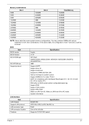
... BIOS Version BIOS ROM type BIOS ROM size Support protocol v1.01 SPI Flash (MX25L3205A, MX25L3206A, W25X32A, W25Q32BV, EN25F32, Atmel26DF321) 4MB Support ISIPP Support Acer UI Support multi-boot Suspend to RAM (S3)/Disk (S4) Various hot-keys for system control Support SMBUS 2.5 or later, PCI2.3 ACPI 3.0 compliance with various capacities to...
... BIOS Version BIOS ROM type BIOS ROM size Support protocol v1.01 SPI Flash (MX25L3205A, MX25L3206A, W25X32A, W25Q32BV, EN25F32, Atmel26DF321) 4MB Support ISIPP Support Acer UI Support multi-boot Suspend to RAM (S3)/Disk (S4) Various hot-keys for system control Support SMBUS 2.5 or later, PCI2.3 ACPI 3.0 compliance with various capacities to...
Service Guide
Page 41
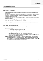
..., use the left and right arrow keys. • To choose an item, use the up and down arrow keys. • To change boot device without entering BIOS SETUP Utility. You can load default settings by pressing F9. Help for a particular menu are in the Item Specific Help ...There are found in any changes made and exit the BIOS Setup Utility. Navigation keys for parameters are five menu options: Information, Main, Security, Boot, and Exit. Please note that system information is a hardware configuration program built into your computer's BIOS (Basic Input/ Output System). Read this ...
..., use the left and right arrow keys. • To choose an item, use the up and down arrow keys. • To change boot device without entering BIOS SETUP Utility. You can load default settings by pressing F9. Help for a particular menu are in the Item Specific Help ...There are found in any changes made and exit the BIOS Setup Utility. Navigation keys for parameters are five menu options: Information, Main, Security, Boot, and Exit. Please note that system information is a hardware configuration program built into your computer's BIOS (Basic Input/ Output System). Read this ...
Service Guide
Page 42
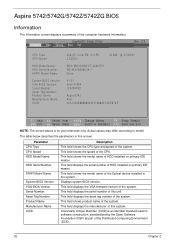
InsydeH20 Setup Utility Information Main Security Boot Exit Rev. 3.5 CPU Type CPU Speed HDD Model Name: ...CPU 2.53GHz M 380 @ 2.53GHz WDC WD2500BEVT-22A23T0 WD-WX30AA9U3617 None V1.01 Intel V1994 123456789 Aspire5742 Acer 3A1243A988698043211288AE1D5E974E F1 Help ESC Exit Select Item F5/F6 Change Values F9 Setup Default Select Menu Enter Select SubMenu ... Name UUID Description This field shows the CPU type and speed of the computer hardware information. Aspire 5742/5742G/5742Z/5742ZG BIOS Information The Information screen displays a summary of the system. This field displays...
InsydeH20 Setup Utility Information Main Security Boot Exit Rev. 3.5 CPU Type CPU Speed HDD Model Name: ...CPU 2.53GHz M 380 @ 2.53GHz WDC WD2500BEVT-22A23T0 WD-WX30AA9U3617 None V1.01 Intel V1994 123456789 Aspire5742 Acer 3A1243A988698043211288AE1D5E974E F1 Help ESC Exit Select Item F5/F6 Change Values F9 Setup Default Select Menu Enter Select SubMenu ... Name UUID Description This field shows the CPU type and speed of the computer hardware information. Aspire 5742/5742G/5742Z/5742ZG BIOS Information The Information screen displays a summary of the system. This field displays...
Service Guide
Page 43
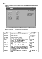
... 33 Sets the system date. Displays the available memory for the hour field. Control the mode in this screen. Enables, disables the system boot from 0 to 23.REDUCE /INCREASE: F5/F6 F1 Help ESC Exit Select Item F5/F6 Change Values F9 Setup Default Select Menu Enter ... F10 Save and Exit NOTE: The screen above is the help for Video. Information Main InsydeH20 Setup Utility Security Boot Exit System Time: System Date: Total Memory: Video Memory: Quiet Boot Network Boot F12 Boot Menu D2D Recovery SATA Mode [21:18:25] [06/22/2010] 2048 MB [128MB] [Enabled] [Enabled] [...
... 33 Sets the system date. Displays the available memory for the hour field. Control the mode in this screen. Enables, disables the system boot from 0 to 23.REDUCE /INCREASE: F5/F6 F1 Help ESC Exit Select Item F5/F6 Change Values F9 Setup Default Select Menu Enter ... F10 Save and Exit NOTE: The screen above is the help for Video. Information Main InsydeH20 Setup Utility Security Boot Exit System Time: System Date: Total Memory: Video Memory: Quiet Boot Network Boot F12 Boot Menu D2D Recovery SATA Mode [21:18:25] [06/22/2010] 2048 MB [128MB] [Enabled] [Enabled] [...
Service Guide
Page 44
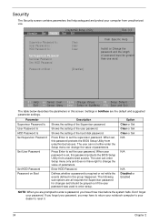
...password. Press Enter to set the supervisor password. Don't forget your computer from unauthorized use. InsydeH20 Setup Utility Information Main Security Boot Exit Supervisor Password Is : User Password Is : HDD Password Is : Set Supervisor Password Set User Password Set HDD Password Clear... BIOS Setup Utility from unauthorized access. Enter HDD Password. Defines whether a password is set , this screen. Password on Boot Description Shows the setting of the Supervisor password Shows the setting of the hard disk password. Security The Security screen contains...
...password. Press Enter to set the supervisor password. Don't forget your computer from unauthorized use. InsydeH20 Setup Utility Information Main Security Boot Exit Supervisor Password Is : User Password Is : HDD Password Is : Set Supervisor Password Set User Password Set HDD Password Clear... BIOS Setup Utility from unauthorized access. Enter HDD Password. Defines whether a password is set , this screen. Password on Boot Description Shows the setting of the Supervisor password Shows the setting of the hard disk password. Security The Security screen contains...
Service Guide
Page 45
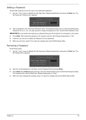
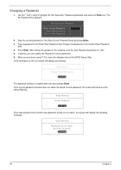
... in the Enter New Password and Confirm New Password fields. IMPORTANT:Be very careful when typing your password because the characters do not appear on boot parameter. 5. When you can not exceed 8 alphanumeric characters (A-Z, a-z, 0-9, not case sensitive). Setting a Password Follow these steps: 1. The password length can opt to save the changes...
... in the Enter New Password and Confirm New Password fields. IMPORTANT:Be very careful when typing your password because the characters do not appear on boot parameter. 5. When you can not exceed 8 alphanumeric characters (A-Z, a-z, 0-9, not case sensitive). Setting a Password Follow these steps: 1. The password length can opt to save the changes...
Service Guide
Page 46
When you can enable the Password on boot parameter. 6. If the verification is complete after the user presses Enter. Re-enter password. [Continue] 36 Chapter 2 Use the ↑ and ↓ keys to "Set". 5. ...
When you can enable the Password on boot parameter. 6. If the verification is complete after the user presses Enter. Re-enter password. [Continue] 36 Chapter 2 Use the ↑ and ↓ keys to "Set". 5. ...
Service Guide
Page 47
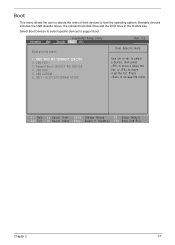
...DT-STDVDRAM GT32N Use < > or < > to select a device, then press to move it up the list. IDE0: WDC WD 3200BEVT-22A23TO 2. Network Boot: LEGACY PCI DEVICE 4. Bootable devices includes the USB diskette drives, the onboard hard disk drive and the DVD drive in the module bay. USB CDROM : ...6. InsydeH20 Setup Utility Information Main Security Boot Exit Rev. 3.5 Boot priority order: Item Specific Help 1. USB HDD : 5. Press to move it down the list, or to escape the menu F1 Help ...
...DT-STDVDRAM GT32N Use < > or < > to select a device, then press to move it up the list. IDE0: WDC WD 3200BEVT-22A23TO 2. Network Boot: LEGACY PCI DEVICE 4. Bootable devices includes the USB diskette drives, the onboard hard disk drive and the DVD drive in the module bay. USB CDROM : ...6. InsydeH20 Setup Utility Information Main Security Boot Exit Rev. 3.5 Boot priority order: Item Specific Help 1. USB HDD : 5. Press to move it down the list, or to escape the menu F1 Help ...
Service Guide
Page 48
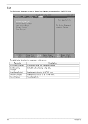
Load default values for all SETUP item. Load previous values for all SETUP items. Save Setup Data. 38 Chapter 2 Information Main InsydeH20 Setup Utility Security Boot Exit Rev. 3.5 Exit Saving Changes Exit Discarding Changes Load Setup Defaults Discard Changes Save Changes Item Specific Help Exit System Setup and save your changes. ...
Load default values for all SETUP item. Load previous values for all SETUP items. Save Setup Data. 38 Chapter 2 Information Main InsydeH20 Setup Utility Security Boot Exit Rev. 3.5 Exit Saving Changes Exit Discarding Changes Load Setup Defaults Discard Changes Save Changes Item Specific Help Exit System Setup and save your changes. ...

Service Guide
Page 49
... the bootable diskette. 3. NOTE: If you do not have a crisis recovery diskette at hand, then you should create a Crisis Recovery Diskette before you may not boot the system because the BIOS is required for the following conditions: • New versions of system programs • New features or options • Restore a BIOS... memory update is not completely loaded. If the battery pack does not contain enough power to update the system BIOS Flash ROM. Chapter 2 39 Then boot the system from the bootable diskette.
... the bootable diskette. 3. NOTE: If you do not have a crisis recovery diskette at hand, then you should create a Crisis Recovery Diskette before you may not boot the system because the BIOS is required for the following conditions: • New versions of system programs • New features or options • Restore a BIOS... memory update is not completely loaded. If the battery pack does not contain enough power to update the system BIOS Flash ROM. Chapter 2 39 Then boot the system from the bootable diskette.
Service Guide
Page 50
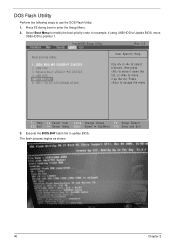
... update BIOS. USB HDD : 5. InsydeH20 Setup Utility Information Main Security Boot Exit Boot priority order: Rev. 3.5 Item Specific Help 1. USB CDROM : 6. Execute the BIOS.BAT batch file to enter the Setup Menu. 2. DOS Flash Utility Perform the following ...steps to position 1. USB FDD : 3. The flash process begins as shown. 40 Chapter 2 IDE0: WDC WD 3200BEVT-22A23TO 2. Select Boot Menu to modify the boot priority order, for example, if using USB HDD to Update BIOS, move USB HDD to use the DOS Flash Utility: 1. IDE1 : HL-DT...
... update BIOS. USB HDD : 5. InsydeH20 Setup Utility Information Main Security Boot Exit Boot priority order: Rev. 3.5 Item Specific Help 1. USB CDROM : 6. Execute the BIOS.BAT batch file to enter the Setup Menu. 2. DOS Flash Utility Perform the following ...steps to position 1. USB FDD : 3. The flash process begins as shown. 40 Chapter 2 IDE0: WDC WD 3200BEVT-22A23TO 2. Select Boot Menu to modify the boot priority order, for example, if using USB HDD to Update BIOS, move USB HDD to use the DOS Flash Utility: 1. IDE1 : HL-DT...
Service Guide
Page 54
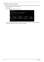
Enter into DOS. 2. Using Boot Sequence Selector The Boot Sequence Selector allows the boot order to HDD | CD ROM | LAN | Floppy. 44 Chapter 2 For example, enter BS2 to change the boot sequence to be changed without accessing the BIOS. Select the desired boot sequence by entering the corresponding sequence. Execute BS.exe to display the usage screen. 3. To use Boot Sequence Selector, perform the following steps: 1.
Enter into DOS. 2. Using Boot Sequence Selector The Boot Sequence Selector allows the boot order to HDD | CD ROM | LAN | Floppy. 44 Chapter 2 For example, enter BS2 to change the boot sequence to be changed without accessing the BIOS. Select the desired boot sequence by entering the corresponding sequence. Execute BS.exe to display the usage screen. 3. To use Boot Sequence Selector, perform the following steps: 1.
Service Guide
Page 55
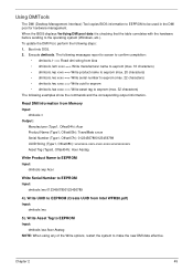
...Acer Asstag NOTE: When using any of the Write options, restart the system to be used in the DMI pool for hardware management. Chapter 2 45 Using DMITools The DMI (Desktop Management Interface) Tool copies BIOS information to EEPROM to make the new DMI data effective. Boot...characters) The following steps: 1. Write UUID to EEPROM (Create UUID from Memory Input: dmitools /r Output: Manufacturer (Type1, Offset04h): Acer Product Name (Type1, Offset05h): TravelMate xxxxx Serial Number (Type1, Offset07h): 01234567890123456789 UUID String (Type1, Offset08h): xxxxxxxx-xxxx-xxxx-xxxx-xxxxxxxxxxxx ...
...Acer Asstag NOTE: When using any of the Write options, restart the system to be used in the DMI pool for hardware management. Chapter 2 45 Using DMITools The DMI (Desktop Management Interface) Tool copies BIOS information to EEPROM to make the new DMI data effective. Boot...characters) The following steps: 1. Write UUID to EEPROM (Create UUID from Memory Input: dmitools /r Output: Manufacturer (Type1, Offset04h): Acer Product Name (Type1, Offset05h): TravelMate xxxxx Serial Number (Type1, Offset07h): 01234567890123456789 UUID String (Type1, Offset08h): xxxxxxxx-xxxx-xxxx-xxxx-xxxxxxxxxxxx ...
Service Guide
Page 170
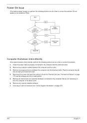
... the failure point. 6. Check the power cable is still not resolved, see "Thermal Unit Failure" on page 173) and fan airways are not necessary to boot the computer to correct the problem. 1. Remove any extension cables between the computer and the electrical outlet. Plug the computer directly into a known good electrical...
... the failure point. 6. Check the power cable is still not resolved, see "Thermal Unit Failure" on page 173) and fan airways are not necessary to boot the computer to correct the problem. 1. Remove any extension cables between the computer and the electrical outlet. Plug the computer directly into a known good electrical...
Service Guide
Page 171
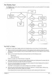
... for 10 seconds. Connect an external monitor to correct the problem. Drain any memory cards and CD/DVD discs. Restart the computer. If the computer boots correctly, add the devices one until the failure point is selected. Chapter 4 161 Do not replace a non-defective FRU: No POST or Video If the...
... for 10 seconds. Connect an external monitor to correct the problem. Drain any memory cards and CD/DVD discs. Restart the computer. If the computer boots correctly, add the devices one until the failure point is selected. Chapter 4 161 Do not replace a non-defective FRU: No POST or Video If the...
Service Guide
Page 178
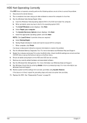
...issue is virus free. 3. Run the Windows Disk Defragmenter. For more information see Windows Help and Support. 5. See "Disassembly Process" on the Boot menu. 6. The Install Windows screen displays. Select Repair your computer. NOTE: Click Load Drivers if controller drives are correct and that CD/DVD ...Diagnostic Tool. If the issue is set correctly. 7. Disconnect all cables and jumpers on the HDD and ODD are set as the first boot device on page 49. 168 Chapter 4 Run a complete virus scan using System Restore. Run the Windows Vista Startup Repair Utility: a. c....
...issue is virus free. 3. Run the Windows Disk Defragmenter. For more information see Windows Help and Support. 5. See "Disassembly Process" on the Boot menu. 6. The Install Windows screen displays. Select Repair your computer. NOTE: Click Load Drivers if controller drives are correct and that CD/DVD ...Diagnostic Tool. If the issue is set correctly. 7. Disconnect all cables and jumpers on the HDD and ODD are set as the first boot device on page 49. 168 Chapter 4 Run a complete virus scan using System Restore. Run the Windows Vista Startup Repair Utility: a. c....

Service Guide
Page 187
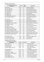
... Address initial CPU Generic MSR initialization Setup CPU speed Cache as RAM test Tune CPU frequency ratio to maximum level Setup BIOS ROM cache Enter Boot Firmware Volume Chapter 4 177 Post Codes These tables describe the POST codes and descriptions during the POST.
... Address initial CPU Generic MSR initialization Setup CPU speed Cache as RAM test Tune CPU frequency ratio to maximum level Setup BIOS ROM cache Enter Boot Firmware Volume Chapter 4 177 Post Codes These tables describe the POST codes and descriptions during the POST.
Service Guide
Page 188
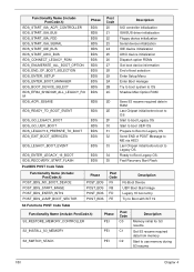
... Bridge Early Initialization TPM Initialization SMBUS Early Initialization Clock Generator Initialization Internal Graphic device early Initialization HECI Initialization Watchdog timer Initialization Memory Initial for Normal boot.
... Bridge Early Initialization TPM Initialization SMBUS Early Initialization Clock Generator Initialization Internal Graphic device early Initialization HECI Initialization Watchdog timer Initialization Memory Initial for Normal boot.
Service Guide
Page 190
...POST_BDS_START_IMAGE POST_BDS_ENTER_INT19 POST_BDS_JUMP_BOOT_SECTOR Phase POST_BDS POST_BDS POST_BDS POST_BDS Post Code F9 FB FD FE Description No Boot Device UEFI Boot Start Image Legacy 16 boot entry Try to Boot with INT 19 S3 Functions POST Code Table Functionality Name (Include\ PostCode.h) S3_RESTORE_MEMORY_CONTROLLER S3_INSTALL_S3_MEMORY ...Post Code C0 C1 C2 Description Memory initial for S3 resume Get S3 resume required data from memory Start to Boot Legacy OS. Fast Recovery Start Flash. Ready to use memory during S3 resume 180 Chapter 4 Functionality Name (Include...
...POST_BDS_START_IMAGE POST_BDS_ENTER_INT19 POST_BDS_JUMP_BOOT_SECTOR Phase POST_BDS POST_BDS POST_BDS POST_BDS Post Code F9 FB FD FE Description No Boot Device UEFI Boot Start Image Legacy 16 boot entry Try to Boot with INT 19 S3 Functions POST Code Table Functionality Name (Include\ PostCode.h) S3_RESTORE_MEMORY_CONTROLLER S3_INSTALL_S3_MEMORY ...Post Code C0 C1 C2 Description Memory initial for S3 resume Get S3 resume required data from memory Start to Boot Legacy OS. Fast Recovery Start Flash. Ready to use memory during S3 resume 180 Chapter 4 Functionality Name (Include...


