
Service Guide
Page 107
LCD Module Disassembly Process LCD Module Disassembly Flowchart Screw List Step LCD Bezel LCD Brackets (top) LCD Hinges Inverter Module LCD Brackets (side) Screw M2.5*6 M2.5*5 M2.5*5 M2.5*5 M2*3 Quantity 2 2 2 1 6 Part No. 86.R4F02.003 86.R4F02.001 86.R4F02.001 86.R4F02.001 86.R4F02.004 Chapter 3 97
LCD Module Disassembly Process LCD Module Disassembly Flowchart Screw List Step LCD Bezel LCD Brackets (top) LCD Hinges Inverter Module LCD Brackets (side) Screw M2.5*6 M2.5*5 M2.5*5 M2.5*5 M2*3 Quantity 2 2 2 1 6 Part No. 86.R4F02.003 86.R4F02.001 86.R4F02.001 86.R4F02.001 86.R4F02.004 Chapter 3 97

Service Guide
Page 114
See "Removing the LCD Bezel" on page 98. 2. Grasp the CCD cable protector box with a plastic tool and pull up to the LCD cover. Removing the LCD/LED Panel 1. Step LCD Brackets Size M2.5*5 LCD Hinges M2.5*5 Quantity 2 2 Screw Type 3. Remove the four (4) screws securing the LCD panel to remove it from the LCD cover. 104 Chapter 3
See "Removing the LCD Bezel" on page 98. 2. Grasp the CCD cable protector box with a plastic tool and pull up to the LCD cover. Removing the LCD/LED Panel 1. Step LCD Brackets Size M2.5*5 LCD Hinges M2.5*5 Quantity 2 2 Screw Type 3. Remove the four (4) screws securing the LCD panel to remove it from the LCD cover. 104 Chapter 3

Service Guide
Page 118
Peel back the foil tabs and remove the microphone cable from the hinge channel. 3. Removing the Microphone Cable 1. Remove the cable bundle from the cable channel. 4. Lift the microphone set clear of the panel. 108 Chapter 3 See "Removing the LCD/LED Panel" on page 104. 2.
Peel back the foil tabs and remove the microphone cable from the hinge channel. 3. Removing the Microphone Cable 1. Remove the cable bundle from the cable channel. 4. Lift the microphone set clear of the panel. 108 Chapter 3 See "Removing the LCD/LED Panel" on page 104. 2.
Service Guide
Page 121
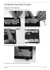
Repeat steps 1 through 3 for the white (left side) antenna assembly. Run the black (right side) antenna along the cable channel and fold over the foil tabs to the LCD cover. 2. Run the cable along the hinge channel. 4. LCD Module Reassembly Procedure Replacing the Antennas 1. Chapter 3 111 Adhere the black (right side) antenna assembly to secure the cable in place. 3.
Repeat steps 1 through 3 for the white (left side) antenna assembly. Run the black (right side) antenna along the cable channel and fold over the foil tabs to the LCD cover. 2. Run the cable along the hinge channel. 4. LCD Module Reassembly Procedure Replacing the Antennas 1. Chapter 3 111 Adhere the black (right side) antenna assembly to secure the cable in place. 3.
Service Guide
Page 127
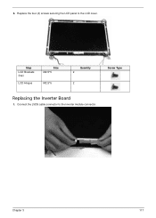
Replace the four (4) screws securing the LCD panel to the inverter module connector. Chapter 3 117 4. Connect the LVDS cable connector to the LCD cover. Step LCD Brackets (top) LCD Hinges Size M2.5*5 M2.5*5 Quantity 2 2 Screw Type Replacing the Inverter Board 1.
Replace the four (4) screws securing the LCD panel to the inverter module connector. Chapter 3 117 4. Connect the LVDS cable connector to the LCD cover. Step LCD Brackets (top) LCD Hinges Size M2.5*5 M2.5*5 Quantity 2 2 Screw Type Replacing the Inverter Board 1.

Service Guide
Page 130
Replace the bezel and press down until there are not trapped by the bezel. 2. IMPORTANT: Ensure that the LCD cables pass through the hinge wells and are no gaps between the bezel and the LCD cover. Secure the two (2) screws and screw caps to the LCD module. Step LCD Bezel Size M2.5*6 Quantity 2 120 Screw Type Chapter 3 Replacing the LCD Bezel 1.
Replace the bezel and press down until there are not trapped by the bezel. 2. IMPORTANT: Ensure that the LCD cables pass through the hinge wells and are no gaps between the bezel and the LCD cover. Secure the two (2) screws and screw caps to the LCD module. Step LCD Bezel Size M2.5*6 Quantity 2 120 Screw Type Chapter 3 Replacing the LCD Bezel 1.


