
English Manual
Page 2
Remove the PART IDENTIFICATION CHART and PART LIST/EXPLODED DRAWING before beginning assembly. 2 TABLE OF CONTENTS IMPORTANT PRECAUTIONS 3 BEFORE YOU BEGIN 4 ASSEMBLY 5 ADJUSTMENTS 14 WEIGHT RESISTANCE CHART 16 TROUBLESHOOTING AND MAINTENANCE 17 CABLE DIAGRAM 18 ORDERING REPLACEMENT PARTS Back Cover LIMITED WARRANTY Back Cover Note: A PART IDENTIFICATION CHART and a PART LIST/EXPLODED DRAWING are attached to the center of this manual.
Remove the PART IDENTIFICATION CHART and PART LIST/EXPLODED DRAWING before beginning assembly. 2 TABLE OF CONTENTS IMPORTANT PRECAUTIONS 3 BEFORE YOU BEGIN 4 ASSEMBLY 5 ADJUSTMENTS 14 WEIGHT RESISTANCE CHART 16 TROUBLESHOOTING AND MAINTENANCE 17 CABLE DIAGRAM 18 ORDERING REPLACEMENT PARTS Back Cover LIMITED WARRANTY Back Cover Note: A PART IDENTIFICATION CHART and a PART LIST/EXPLODED DRAWING are attached to the center of this manual.
English Manual
Page 3
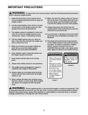
... all of 35 or persons with great force. Apply the decal in the locations shown on a level surface. Keep hands and feet away from the weight system at all parts are exercising, stop immediately and begin cooling down. 15. Keep hands and fingers clear of this manual and in any exercise... shoes for persons over the age of the pulleys. 13. Never release the press arm, butterfly arms, leg lever, lat bar, or nylon strap while weights are adequately informed of the owner to protect the floor. 5. It is missing or illegible, call our toll-free Customer Hot Line at any worn...
... all of 35 or persons with great force. Apply the decal in the locations shown on a level surface. Keep hands and feet away from the weight system at all parts are exercising, stop immediately and begin cooling down. 15. Keep hands and fingers clear of this manual and in any exercise... shoes for persons over the age of the pulleys. 13. Never release the press arm, butterfly arms, leg lever, lat bar, or nylon strap while weights are adequately informed of the owner to protect the floor. 5. It is missing or illegible, call our toll-free Customer Hot Line at any worn...
English Manual
Page 4
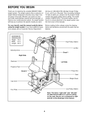
...p.m. ASSEMBLED DIMENSIONS: Height: 76 in . Length: 44 in . they do not correspond to achieve the specific results you for selecting the versatile WEIDER® 8525 weight system. BEFORE YOU BEGIN Thank you want. The serial number can be found on the drawings in . If you , please note the product... model number and serial number before using the weight system. To help you to right and left side" are labeled. Butterfly ...
...p.m. ASSEMBLED DIMENSIONS: Height: 76 in . Length: 44 in . they do not correspond to achieve the specific results you for selecting the versatile WEIDER® 8525 weight system. BEFORE YOU BEGIN Thank you want. The serial number can be found on the drawings in . If you , please note the product... model number and serial number before using the weight system. To help you to right and left side" are labeled. Butterfly ...
English Manual
Page 5
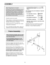
..., it is completed. • Tighten all parts as you assemble them, unless instructed to do otherwise. • As you assemble the weight system, make sure that you have read and understand the information in the center of this manual. The following tools (not included) are ... x 2 1/2" Carriage Bolts (1) up through the Base (4). Attach the indicated end of the Base (4) to realize that the weight system has many parts and that the weight system can be assembled successfully by setting aside plenty of the packing materials until assembly is important to the Stabilizer (5) with two...
..., it is completed. • Tighten all parts as you assemble them, unless instructed to do otherwise. • As you assemble the weight system, make sure that you have read and understand the information in the center of this manual. The following tools (not included) are ... x 2 1/2" Carriage Bolts (1) up through the Base (4). Attach the indicated end of the Base (4) to realize that the weight system has many parts and that the weight system can be assembled successfully by setting aside plenty of the packing materials until assembly is important to the Stabilizer (5) with two...
English Manual
Page 6
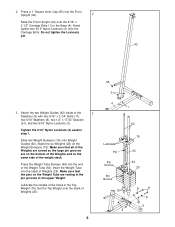
...16" Nylon Locknuts (3) used in the Base (4). Press the Weight Tube Bumper (64) into the stack of the Weight Tube (63). Slide two Weight Bumpers (19) onto Weight Guides (62). Insert the Weight Tube into the end of Weights (25). Lubricate the insides of Weights (25). 6 65 3 4 1 62 Lubricate Pin Pin ... turned so the large pin grooves are resting in the pin grooves in the Top Weight (76). Stack the six Weights (25) on the same side of the Weights and on the Weight Bumpers (19). 2. Make sure that all of the 3 Stabilizer (5) with two 5/16" x 2 3/4" Bolts (11), two 5/16" Washers ...
...16" Nylon Locknuts (3) used in the Base (4). Press the Weight Tube Bumper (64) into the stack of the Weight Tube (63). Slide two Weight Bumpers (19) onto Weight Guides (62). Insert the Weight Tube into the end of Weights (25). Lubricate the insides of Weights (25). 6 65 3 4 1 62 Lubricate Pin Pin ... turned so the large pin grooves are resting in the pin grooves in the Top Weight (76). Stack the six Weights (25) on the same side of the Weights and on the Weight Bumpers (19). 2. Make sure that all of the 3 Stabilizer (5) with two 5/16" x 2 3/4" Bolts (11), two 5/16" Washers ...
English Manual
Page 7
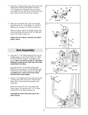
Press two 2" Square Inner Caps (27) into the top of the Weight Guides (62) to the Base (4) with the Bolt and a 3/8" Nylon Locknut (21). Attach the upper ends of the crossbar. 78 55 27 5. Press two 1" x 7/8" Plastic ...
Press two 2" Square Inner Caps (27) into the top of the Weight Guides (62) to the Base (4) with the Bolt and a 3/8" Nylon Locknut (21). Attach the upper ends of the crossbar. 78 55 27 5. Press two 1" x 7/8" Plastic ...
English Manual
Page 11
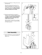
... a 3 67 5/16" Nylon Locknut (3). 72 10 63 2 23 2 67 Seat Assembly 21 21. Do not overtighten the Nylon Locknut; Attach the Backrest (41) to the Weight Tube (63) with the 3/8" x 2" Bolt (12) and the 3/8" Nylon Locknut (21). 19.
... a 3 67 5/16" Nylon Locknut (3). 72 10 63 2 23 2 67 Seat Assembly 21 21. Do not overtighten the Nylon Locknut; Attach the Backrest (41) to the Weight Tube (63) with the 3/8" x 2" Bolt (12) and the 3/8" Nylon Locknut (21). 19.
English Manual
Page 13
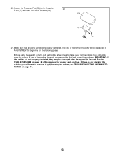
... been properly tightened. See the CABLE DIAGRAM on page 17. 13 IMPORTANT: If the cables are not properly installed, they may be damaged when heavy weight is any slack in the cables, you will be explained in ADJUSTMENTS, beginning on the following page. 26. Attach the Preacher Pad (56) to remove...
... been properly tightened. See the CABLE DIAGRAM on page 17. 13 IMPORTANT: If the cables are not properly installed, they may be damaged when heavy weight is any slack in the cables, you will be explained in ADJUSTMENTS, beginning on the following page. 26. Attach the Preacher Pad (56) to remove...
English Manual
Page 14
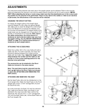
...pin on page 16 to find the actual amount of the exercise will be removed. CHANGING THE WEIGHT SETTING To change the weight setting of the weight system can be adjusted. The weight setting of the weight stack can be changed from the front upright before the Short Cable (not shown) is used.... (See ATTACHING AND REMOVING THE SEAT, below describe how each part of the weight stack, insert the Weight Pin (26) under the desired Weight (25). The accessories can be attached to the Short Cable (not shown) in the correct starting position for the exercise...
...pin on page 16 to find the actual amount of the exercise will be removed. CHANGING THE WEIGHT SETTING To change the weight setting of the weight system can be adjusted. The weight setting of the weight stack can be changed from the front upright before the Short Cable (not shown) is used.... (See ATTACHING AND REMOVING THE SEAT, below describe how each part of the weight stack, insert the Weight Pin (26) under the desired Weight (25). The accessories can be attached to the Short Cable (not shown) in the correct starting position for the exercise...
English Manual
Page 16
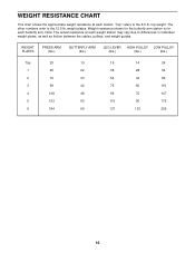
The other numbers refer to differences in individual weight plates, as well as friction between the cables, pulleys, and weight guides. weight plates. Weight resistance shown for the butterfly arm station is for each butterfly arm. WEIGHT PLATES PRESS ARM (lbs.) BUTTERFLY ARM (lbs.) LEG LEVER HIGH PULLEY LOW PULLEY ...48 96 72 147 60 115 90 175 69 137 103 209 16 top weight. Note: The actual resistance at each station. WEIGHT RESISTANCE CHART This chart shows the approximate weight resistance at each weight station may vary due to the 12.5 lb. "Top" refers to the...
The other numbers refer to differences in individual weight plates, as well as friction between the cables, pulleys, and weight guides. weight plates. Weight resistance shown for the butterfly arm station is for each butterfly arm. WEIGHT PLATES PRESS ARM (lbs.) BUTTERFLY ARM (lbs.) LEG LEVER HIGH PULLEY LOW PULLEY ...48 96 72 147 60 115 90 175 69 137 103 209 16 top weight. Note: The actual resistance at each station. WEIGHT RESISTANCE CHART This chart shows the approximate weight resistance at each weight station may vary due to the 12.5 lb. "Top" refers to the...
English Manual
Page 17
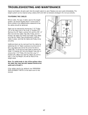
...the 3/8" Nylon Locknut (21) and the 3/8" x 2" Bolt (12) from the cables by moving the 3 1/2" Pulley (15) to remove the Small "U"-bracket (67) from the Weight Tube (63) or remove the 3 1/2" Pulley (15) from the Long "U"bracket (57). Re-attach the Pulley and Cable Trap. Remove the cable and re-install... THE CABLES Woven cable, the type of cable used . Do not use solvents. Additional slack can be replaced, see ORDERING REPLACEMENT PARTS on the weight system, can be lifted off the pulleys often, the cable may need to be removed from the Cable Trap (66), Pulley, and "U"bracket. If...
...the 3/8" Nylon Locknut (21) and the 3/8" x 2" Bolt (12) from the cables by moving the 3 1/2" Pulley (15) to remove the Small "U"-bracket (67) from the Weight Tube (63) or remove the 3 1/2" Pulley (15) from the Long "U"bracket (57). Re-attach the Pulley and Cable Trap. Remove the cable and re-install... THE CABLES Woven cable, the type of cable used . Do not use solvents. Additional slack can be replaced, see ORDERING REPLACEMENT PARTS on the weight system, can be lifted off the pulleys often, the cable may need to be removed from the Cable Trap (66), Pulley, and "U"bracket. If...
English Manual
Page 18
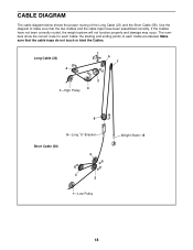
... the correct route for each Cable are labeled. Make sure that the two Cables and the cable traps have not been correctly routed, the weight system will not function properly and damage may occur. If the Cables have been assembled correctly. the starting and ending points of the Long... Cable (23) and the Short Cable (58). Long Cable (23) 4 5 7 2 3 1-High Pulley 6 5-Long "U"-Bracket Short Cable (58) 4 3 2 1-Low Pulley Weight Stack-8 18 CABLE DIAGRAM The cable diagram below shows the proper routing of each Cable; Use the diagram to make sure that the cable traps...
... the correct route for each Cable are labeled. Make sure that the two Cables and the cable traps have not been correctly routed, the weight system will not function properly and damage may occur. If the Cables have been assembled correctly. the starting and ending points of the Long... Cable (23) and the Short Cable (58). Long Cable (23) 4 5 7 2 3 1-High Pulley 6 5-Long "U"-Bracket Short Cable (58) 4 3 2 1-Low Pulley Weight Stack-8 18 CABLE DIAGRAM The cable diagram below shows the proper routing of each Cable; Use the diagram to make sure that the cable traps...
English Manual
Page 21
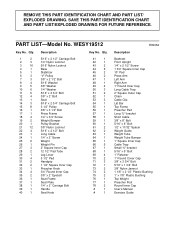
... Bolt Seat 5/16" x 2 3/4" Carriage Bolt 3 1/2" Pulley 3/8" x 3 1/2" Bolt Press Frame 1/4" x 3/4" Screw Weight Bumper Pulley Bracket 3/8" Nylon Locknut 5/16" x 2 1/2" Bolt Long Cable 1/4" x 2" Screw Weight Weight Pin 2" Square Inner Cap 12 1/2" Pad Tube Leg Lever 5 1/2" Pad Handgrip 1 1/2" Square Inner Cap Preacher Knob 3/4" ...Clip Lat Bar Top Frame Preacher Pad Long "U"-bracket Short Cable 3/8" x 8" Bolt 5/16" x 6" Bolt 1/2" x 17/32" Spacer Weight Guide Weight Tube Weight Tube Bumper 1" Square Inner Cap Cable Trap Small "U"-bracket 5/16" x 5" Bolt 1" Retainer 1" Round Cover Cap 3/8" x 3 3/4"...
... Bolt Seat 5/16" x 2 3/4" Carriage Bolt 3 1/2" Pulley 3/8" x 3 1/2" Bolt Press Frame 1/4" x 3/4" Screw Weight Bumper Pulley Bracket 3/8" Nylon Locknut 5/16" x 2 1/2" Bolt Long Cable 1/4" x 2" Screw Weight Weight Pin 2" Square Inner Cap 12 1/2" Pad Tube Leg Lever 5 1/2" Pad Handgrip 1 1/2" Square Inner Cap Preacher Knob 3/4" ...Clip Lat Bar Top Frame Preacher Pad Long "U"-bracket Short Cable 3/8" x 8" Bolt 5/16" x 6" Bolt 1/2" x 17/32" Spacer Weight Guide Weight Tube Weight Tube Bumper 1" Square Inner Cap Cable Trap Small "U"-bracket 5/16" x 5" Bolt 1" Retainer 1" Round Cover Cap 3/8" x 3 3/4"...
English Manual
Page 23
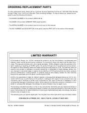
... this product to be prepared to give the following information: • The MODEL NUMBER of the product (WESY19512) • The NAME of the product (WEIDER® 8525 weight system) • The SERIAL NUMBER of the product (see the front cover of this manual) • The KEY NUMBER and DESCRIPTION of the part(s) (see...
... this product to be prepared to give the following information: • The MODEL NUMBER of the product (WESY19512) • The NAME of the product (WEIDER® 8525 weight system) • The SERIAL NUMBER of the product (see the front cover of this manual) • The KEY NUMBER and DESCRIPTION of the part(s) (see...


