
English Manual
Page 2
Remove the PART IDENTIFICATION CHART and PART LIST/EXPLODED DRAWING before beginning assembly. 2 TABLE OF CONTENTS IMPORTANT PRECAUTIONS 3 BEFORE YOU BEGIN 4 ASSEMBLY 5 ADJUSTMENTS 14 WEIGHT RESISTANCE CHART 16 TROUBLESHOOTING AND MAINTENANCE 17 CABLE DIAGRAM 18 ORDERING REPLACEMENT PARTS Back Cover LIMITED WARRANTY Back Cover Note: A PART IDENTIFICATION CHART and a PART LIST/EXPLODED DRAWING are attached to the center of this manual.
Remove the PART IDENTIFICATION CHART and PART LIST/EXPLODED DRAWING before beginning assembly. 2 TABLE OF CONTENTS IMPORTANT PRECAUTIONS 3 BEFORE YOU BEGIN 4 ASSEMBLY 5 ADJUSTMENTS 14 WEIGHT RESISTANCE CHART 16 TROUBLESHOOTING AND MAINTENANCE 17 CABLE DIAGRAM 18 ORDERING REPLACEMENT PARTS Back Cover LIMITED WARRANTY Back Cover Note: A PART IDENTIFICATION CHART and a PART LIST/EXPLODED DRAWING are attached to the center of this manual.
English Manual
Page 3
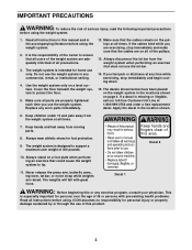
... product. 3 Decal 2 10. Decal 1 WARNING: Before beginning this manual and in any time while exercising, stop immediately and make sure that the cables remain on the weight system in the location shown. 6. Read all parts are properly tightened each time you use the weight system. Make sure that... the cables are exercising, stop immediately and begin cooling down. 15. If the cables bind while you feel pain or dizziness at all of the pulleys. 13. Keep children under 12 and ...
... product. 3 Decal 2 10. Decal 1 WARNING: Before beginning this manual and in any time while exercising, stop immediately and make sure that the cables remain on the weight system in the location shown. 6. Read all parts are properly tightened each time you use the weight system. Make sure that... the cables are exercising, stop immediately and begin cooling down. 15. If the cables bind while you feel pain or dizziness at all of the pulleys. 13. Keep children under 12 and ...
English Manual
Page 8
... on the Top Frame. 70 47 Tap two 1" Retainers (69) and a 1" Round Cover Cap (70) onto the right axle. Attach the Pulley and a Cable Trap (66) to the CABLE DIAGRAM on page 18 of the Left Arm (47). Press a 1 3/4" Square Inner Cap (44) into the lower end of this manual to confuse... the Right Arm (48) with a 3/8" x 2" Bolt (12) and a 3/8" Nylon Locknut (21). Note: Be careful not to verify proper cable routing. Make sure that the Cable Trap is turned to the bracket with the Left Arm. Wet the end of the Left Arm is on the indicated side of...
... on the Top Frame. 70 47 Tap two 1" Retainers (69) and a 1" Round Cover Cap (70) onto the right axle. Attach the Pulley and a Cable Trap (66) to the CABLE DIAGRAM on page 18 of the Left Arm (47). Press a 1 3/4" Square Inner Cap (44) into the lower end of this manual to confuse... the Right Arm (48) with a 3/8" x 2" Bolt (12) and a 3/8" Nylon Locknut (21). Note: Be careful not to verify proper cable routing. Make sure that the Cable Trap is turned to the bracket with the Left Arm. Wet the end of the Left Arm is on the indicated side of...
English Manual
Page 9
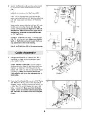
... x 3 3/4" Bolt (71), a 3/8" Washer (9), and a 3/8" Nylon Locknut (21). See the inset drawing. It is turned to the upper hole in place and that the Cable Trap (66) is shown exploded in this drawing for clarity. 11. Note: The 3 1/2" Pulley (15) in this step has been preassembled. Make sure that the... Cable is turned to the Top Frame (55). Tighten the 3/8" x 3 3/4" Bolt (71) and the 3/8" Nylon Locknut (21). 14 21 55 Hook 23 15...
... x 3 3/4" Bolt (71), a 3/8" Washer (9), and a 3/8" Nylon Locknut (21). See the inset drawing. It is turned to the upper hole in place and that the Cable Trap (66) is shown exploded in this drawing for clarity. 11. Note: The 3 1/2" Pulley (15) in this step has been preassembled. Make sure that the... Cable is turned to the Top Frame (55). Tighten the 3/8" x 3 3/4" Bolt (71) and the 3/8" Nylon Locknut (21). 14 21 55 Hook 23 15...
English Manual
Page 10
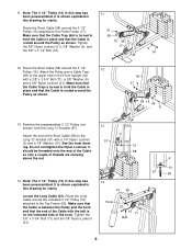
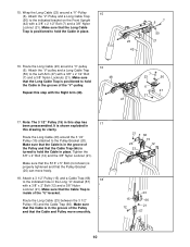
... 20 23 66 15 12 15 12 23 66 21 57 10 Make sure that the 5/16" x 5" Bolt (not shown) is turned to hold the Cable in the Long "U"-bracket (57) with the Right Arm (48). 16 48 47 7 23 50 6 47 21 17. 15. Route the Long... 21 16. Tighten the 3/8" x 2" Bolt (12) and the 3/8" Nylon Locknut (21). Attach a 3 1/2" Pulley (15) and a Cable Trap (66) 18 to the Pulley Bracket (20). Wrap the Long Cable (23) around a "V"-Pulley 15 (6). Attach the "V"-Pulley and a Long Cable Trap (50) to the Left Arm (47) with a 3/8" x 2 1/2" Bolt (7) and a 3/8" Nylon Locknut (21). Attach the...
... 20 23 66 15 12 15 12 23 66 21 57 10 Make sure that the 5/16" x 5" Bolt (not shown) is turned to hold the Cable in the Long "U"-bracket (57) with the Right Arm (48). 16 48 47 7 23 50 6 47 21 17. 15. Route the Long... 21 16. Tighten the 3/8" x 2" Bolt (12) and the 3/8" Nylon Locknut (21). Attach a 3 1/2" Pulley (15) and a Cable Trap (66) 18 to the Pulley Bracket (20). Wrap the Long Cable (23) around a "V"-Pulley 15 (6). Attach the "V"-Pulley and a Long Cable Trap (50) to the Left Arm (47) with a 3/8" x 2 1/2" Bolt (7) and a 3/8" Nylon Locknut (21). Attach the...
English Manual
Page 11
... "U"- 20 bracket (67) with the 5/16" x 1 3/4" Bolt (72) and a 3 67 5/16" Nylon Locknut (3). 72 10 63 2 23 2 67 Seat Assembly 21 21. Attach the Long Cable (23) to the bracket on the Top Frame (55) with two 1/4" x 2 1/2" Screws (43) and two 1/4" Washers (10). 41 43 10 42 43 10 11 Do... the indicated 3 1/2" Pulley (15) from the Top Frame (55). 19 Route the Long Cable (23) around the 3 1/2" Pulley (15) and reattach it should be threaded onto the end of the Cable only a couple of the Pulley and that the Cable and Pulley move smoothly. 21 55 Bracket 15 12 23 20. 19. Make...
... "U"- 20 bracket (67) with the 5/16" x 1 3/4" Bolt (72) and a 3 67 5/16" Nylon Locknut (3). 72 10 63 2 23 2 67 Seat Assembly 21 21. Attach the Long Cable (23) to the bracket on the Top Frame (55) with two 1/4" x 2 1/2" Screws (43) and two 1/4" Washers (10). 41 43 10 42 43 10 11 Do... the indicated 3 1/2" Pulley (15) from the Top Frame (55). 19 Route the Long Cable (23) around the 3 1/2" Pulley (15) and reattach it should be threaded onto the end of the Cable only a couple of the Pulley and that the Cable and Pulley move smoothly. 21 55 Bracket 15 12 23 20. 19. Make...
English Manual
Page 13
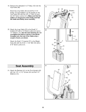
... parts will need to remove it by tightening the cables; If one of this manual for proper cable routing. see TROUBLESHOOTING AND MAINTENANCE on page 18 of the cables does not move smoothly over the pulleys. Before using the weight system, pull each cable a few times to the Preacher 26 Post (77...) with two 1/4" x 3/4" Screws (18). 56 77 18 27. Make sure that the cables move smoothly, find and correct the problem. See the CABLE DIAGRAM on page 17. 13 26. Attach the Preacher Pad (56) to make sure that all parts have been properly tightened....
... parts will need to remove it by tightening the cables; If one of this manual for proper cable routing. see TROUBLESHOOTING AND MAINTENANCE on page 18 of the cables does not move smoothly over the pulleys. Before using the weight system, pull each cable a few times to the Preacher 26 Post (77...) with two 1/4" x 3/4" Screws (18). 56 77 18 27. Make sure that the cables move smoothly, find and correct the problem. See the CABLE DIAGRAM on page 17. 13 26. Attach the Preacher Pad (56) to make sure that all parts have been properly tightened....
English Manual
Page 14
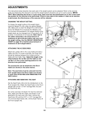
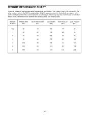
...amount of resistance at each exercise station may vary from 6.5 pounds to 81.5 pounds, in increments of 12.5 pounds. Note: Due to the cables and pulleys, the actual amount of resistance at each weight station. 25 26 ATTACHING THE ACCESSORIES Attach the Lat Bar (54) to the Leg Lever... accessories can be reduced. Note: The seat frame must be removed. First, make sure that the Chain (not shown) is not attached to the Long Cable (23) with a 5/16" x 2 3/4" Carriage Bolt (14) and the Seat Knob (40). Refer to the exercise guide accompanying this manual to be performed. ...
...amount of resistance at each exercise station may vary from 6.5 pounds to 81.5 pounds, in increments of 12.5 pounds. Note: Due to the cables and pulleys, the actual amount of resistance at each weight station. 25 26 ATTACHING THE ACCESSORIES Attach the Lat Bar (54) to the Leg Lever... accessories can be reduced. Note: The seat frame must be removed. First, make sure that the Chain (not shown) is not attached to the Long Cable (23) with a 5/16" x 2 3/4" Carriage Bolt (14) and the Seat Knob (40). Refer to the exercise guide accompanying this manual to be performed. ...
English Manual
Page 15
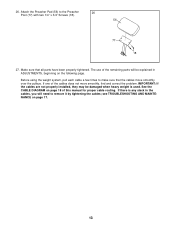
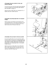
... Lat Bar (54) with the Preacher Knob (33). Attach one end of a Chain (52) to the Seat Frame with a Cable Clip (53). Attach the other end of the Preacher Post (77) around the 5/16" x 2 3/4" Bolt (not shown) ... TO THE LOW PULLEY STATION To use the Lat Bar (54) to do curl exercises, attach the short cable to the leg lever, and the preacher pad (not shown) to the front upright (see ATTACHING THE LEG... STATION and ATTACHING THE PREACHER PAD TO THE SEAT FRAME, above). Attach the Short Cable (58) to the indicated 3/8" x 2" Eyebolt (35) on the bottom of the Chain to the indicated 3/8" x 2" ...
... Lat Bar (54) with the Preacher Knob (33). Attach one end of a Chain (52) to the Seat Frame with a Cable Clip (53). Attach the other end of the Preacher Post (77) around the 5/16" x 2 3/4" Bolt (not shown) ... TO THE LOW PULLEY STATION To use the Lat Bar (54) to do curl exercises, attach the short cable to the leg lever, and the preacher pad (not shown) to the front upright (see ATTACHING THE LEG... STATION and ATTACHING THE PREACHER PAD TO THE SEAT FRAME, above). Attach the Short Cable (58) to the indicated 3/8" x 2" Eyebolt (35) on the bottom of the Chain to the indicated 3/8" x 2" ...
English Manual
Page 16
... chart shows the approximate weight resistance at each weight station may vary due to differences in individual weight plates, as well as friction between the cables, pulleys, and weight guides. "Top" refers to the 12.5 lb.
... chart shows the approximate weight resistance at each weight station may vary due to differences in individual weight plates, as well as friction between the cables, pulleys, and weight guides. "Top" refers to the 12.5 lb.
English Manual
Page 17
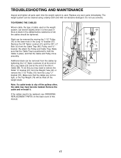
...the Weight Tube (63) or remove the 3 1/2" Pulley (15) from the Long "U"bracket (57). TIGHTENING THE CABLES Woven cable, the type of cable used on the back cover of the Short Cable (58). Slack can be replaced, see ORDERING REPLACEMENT PARTS on the weight system, can stretch slightly when it . ...Remove the 3/8" Nylon Locknut (21) and the 3/8" x 2" Bolt (12) from the cables by moving the 3 1/2" Pulley (15) to hold the Cable in the cables before resistance is felt, the cables should be cleaned using a damp cloth and mild non-abrasive detergent. Re-attach the Pulley and...
...the Weight Tube (63) or remove the 3 1/2" Pulley (15) from the Long "U"bracket (57). TIGHTENING THE CABLES Woven cable, the type of cable used on the back cover of the Short Cable (58). Slack can be replaced, see ORDERING REPLACEMENT PARTS on the weight system, can stretch slightly when it . ...Remove the 3/8" Nylon Locknut (21) and the 3/8" x 2" Bolt (12) from the cables by moving the 3 1/2" Pulley (15) to hold the Cable in the cables before resistance is felt, the cables should be cleaned using a damp cloth and mild non-abrasive detergent. Re-attach the Pulley and...
English Manual
Page 18
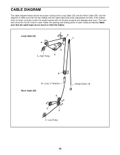
... Weight Stack-8 18 The numbers show the correct route for each Cable are labeled. the starting and ending points of the Long Cable (23) and the Short Cable (58). If the Cables have been assembled correctly. Make sure that the two Cables and the cable traps have not been correctly routed, the weight system will not...
... Weight Stack-8 18 The numbers show the correct route for each Cable are labeled. the starting and ending points of the Long Cable (23) and the Short Cable (58). If the Cables have been assembled correctly. Make sure that the two Cables and the cable traps have not been correctly routed, the weight system will not...
English Manual
Page 21
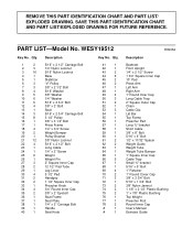
...Square Inner Cap 10" Pad Press Arm Left Arm Right Arm 1" Round Inner Cap Long Cable Trap 2" Square Outer Cap Chain Cable Clip Lat Bar Top Frame Preacher Pad Long "U"-bracket Short Cable 3/8" x 8" Bolt 5/16" x 6" Bolt 1/2" x 17/32" Spacer Weight ...Seat 5/16" x 2 3/4" Carriage Bolt 3 1/2" Pulley 3/8" x 3 1/2" Bolt Press Frame 1/4" x 3/4" Screw Weight Bumper Pulley Bracket 3/8" Nylon Locknut 5/16" x 2 1/2" Bolt Long Cable 1/4" x 2" Screw Weight Weight Pin 2" Square Inner Cap 12 1/2" Pad Tube Leg Lever 5 1/2" Pad Handgrip 1 1/2" Square Inner Cap Preacher Knob 3/4" Round Inner Cap 3/8" x 2" Eyebolt...
...Square Inner Cap 10" Pad Press Arm Left Arm Right Arm 1" Round Inner Cap Long Cable Trap 2" Square Outer Cap Chain Cable Clip Lat Bar Top Frame Preacher Pad Long "U"-bracket Short Cable 3/8" x 8" Bolt 5/16" x 6" Bolt 1/2" x 17/32" Spacer Weight ...Seat 5/16" x 2 3/4" Carriage Bolt 3 1/2" Pulley 3/8" x 3 1/2" Bolt Press Frame 1/4" x 3/4" Screw Weight Bumper Pulley Bracket 3/8" Nylon Locknut 5/16" x 2 1/2" Bolt Long Cable 1/4" x 2" Screw Weight Weight Pin 2" Square Inner Cap 12 1/2" Pad Tube Leg Lever 5 1/2" Pad Handgrip 1 1/2" Square Inner Cap Preacher Knob 3/4" Round Inner Cap 3/8" x 2" Eyebolt...


