
English Manual
Page 8
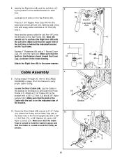
..., refer to confuse the Right Arm (48) with a 3/8" x 3 3/4" Bolt (71), a 3/8" Washer (9), and a 3/8" Nylon Locknut (21). Attach the Pulley and a Cable Trap (66) to verify proper cable routing. 8. Identify the Right Arm (48) and the Left Arm (47) 8 by the position of the welded bracket on page 18 of the Left... (55). Wet the end of the Left Arm (47). Locate the Short Cable (58). Make sure that the Cable is behind the indicated bracket on the Base (4) and under the Press Frame (17). Route the Short Cable (58) around the Pulley as shown in the inset drawing. 44 69 45...
..., refer to confuse the Right Arm (48) with a 3/8" x 3 3/4" Bolt (71), a 3/8" Washer (9), and a 3/8" Nylon Locknut (21). Attach the Pulley and a Cable Trap (66) to verify proper cable routing. 8. Identify the Right Arm (48) and the Left Arm (47) 8 by the position of the welded bracket on page 18 of the Left... (55). Wet the end of the Left Arm (47). Locate the Short Cable (58). Make sure that the Cable is behind the indicated bracket on the Base (4) and under the Press Frame (17). Route the Short Cable (58) around the Pulley as shown in the inset drawing. 44 69 45...
English Manual
Page 9
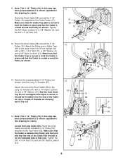
...this step has been preassembled. Make sure that the end of threads are showing above the nut. 13 57 2 10 58 14. 11. Route the Short Cable (58) around the indicated 3 1/2" Pulley (15) attached to the Long "U"-bracket (57) with the ball is between the Pulley and the... the 3/8" Nylon Locknut (21). 14 21 55 Hook 23 15 71 Ball 2 10 57 58 9 Note: The 3 1/2" Pulley (15) in this drawing for clarity. Route the Short Cable (58) around the Pulley as shown. Note: The 3 1/2" Pulley (15) in the Front Upright (42) with a 3/8" x 3 3/4" Bolt (71), a 3/8" Washer (9), and a 3/8" ...
...this step has been preassembled. Make sure that the end of threads are showing above the nut. 13 57 2 10 58 14. 11. Route the Short Cable (58) around the indicated 3 1/2" Pulley (15) attached to the Long "U"-bracket (57) with the ball is between the Pulley and the... the 3/8" Nylon Locknut (21). 14 21 55 Hook 23 15 71 Ball 2 10 57 58 9 Note: The 3 1/2" Pulley (15) in this drawing for clarity. Route the Short Cable (58) around the Pulley as shown. Note: The 3 1/2" Pulley (15) in the Front Upright (42) with a 3/8" x 3 3/4" Bolt (71), a 3/8" Washer (9), and a 3/8" ...
English Manual
Page 10
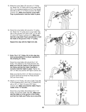
... the Long "U"-bracket (57) with the Right Arm (48). 16 48 47 7 23 50 6 47 21 17. Make sure that the Cable and Pulley move freely. 18. Route the Long Cable (23) around a "V"-Pulley 15 (6). Note: The 3 1/2" Pulley (15) in the groove of the "U"-bracket. Tighten the 3/8" x 2"... 57 10 15. Repeat this step has 17 been preassembled. Route the Long Cable (23) between the 3 1/2" Pulley (15) and the Cable Trap (66). It is inside of the "V"-pulley. Route the Long Cable (23) around the 3 1/2" Pulley (15) attached to hold the Cable in this step with a 3/8" x 2" Bolt (12) ...
... the Long "U"-bracket (57) with the Right Arm (48). 16 48 47 7 23 50 6 47 21 17. Make sure that the Cable and Pulley move freely. 18. Route the Long Cable (23) around a "V"-Pulley 15 (6). Note: The 3 1/2" Pulley (15) in the groove of the "U"-bracket. Tighten the 3/8" x 2"... 57 10 15. Repeat this step has 17 been preassembled. Route the Long Cable (23) between the 3 1/2" Pulley (15) and the Cable Trap (66). It is inside of the "V"-pulley. Route the Long Cable (23) around the 3 1/2" Pulley (15) attached to hold the Cable in this step with a 3/8" x 2" Bolt (12) ...
English Manual
Page 11
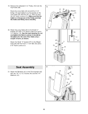
... 11 Remove the indicated 3 1/2" Pulley (15) from the Top Frame (55). 19 Route the Long Cable (23) around the 3 1/2" Pulley (15) and reattach it should be threaded onto the end of the Cable only a couple of the Pulley and that the Cable and Pulley move smoothly. 21 55 Bracket 15 12 23 20. Make... sure that the Cable is in the groove of turns, as shown. 23 Attach the Small "U"-bracket (67...
... 11 Remove the indicated 3 1/2" Pulley (15) from the Top Frame (55). 19 Route the Long Cable (23) around the 3 1/2" Pulley (15) and reattach it should be threaded onto the end of the Cable only a couple of the Pulley and that the Cable and Pulley move smoothly. 21 55 Bracket 15 12 23 20. Make... sure that the Cable is in the groove of turns, as shown. 23 Attach the Small "U"-bracket (67...
English Manual
Page 13
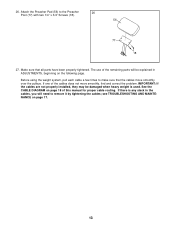
26. The use of this manual for proper cable routing. See the CABLE DIAGRAM on page 18 of the remaining parts will need to remove it by tightening the cables; see TROUBLESHOOTING AND MAINTENANCE on the following page. Before using the weight system, pull each cable a few times to the Preacher 26 Post ... over the pulleys. If there is any slack in ADJUSTMENTS, beginning on page 17. 13 IMPORTANT: If the cables are not properly installed, they may be explained in the cables, you will be damaged when heavy weight is used. Attach the Preacher Pad (56) to make sure that...
26. The use of this manual for proper cable routing. See the CABLE DIAGRAM on page 18 of the remaining parts will need to remove it by tightening the cables; see TROUBLESHOOTING AND MAINTENANCE on the following page. Before using the weight system, pull each cable a few times to the Preacher 26 Post ... over the pulleys. If there is any slack in ADJUSTMENTS, beginning on page 17. 13 IMPORTANT: If the cables are not properly installed, they may be explained in the cables, you will be damaged when heavy weight is used. Attach the Preacher Pad (56) to make sure that...
English Manual
Page 18
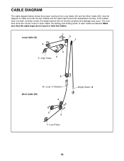
... and ending points of the Long Cable (23) and the Short Cable (58). Make sure that the two Cables and the cable traps have not been correctly routed, the weight system will not function properly and damage may occur. CABLE DIAGRAM The cable diagram below shows the proper routing of each Cable; If the Cables have been assembled correctly. Use...
... and ending points of the Long Cable (23) and the Short Cable (58). Make sure that the two Cables and the cable traps have not been correctly routed, the weight system will not function properly and damage may occur. CABLE DIAGRAM The cable diagram below shows the proper routing of each Cable; If the Cables have been assembled correctly. Use...


