XM Satellite Radio Operating manual
Page 2
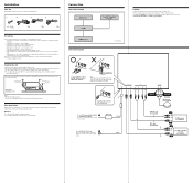
... Car Audio* Cautions • This unit is not subject to temperatures exceeding 55°C (131°F) (such as in a car parked in direct sunlight). - POWER SONY BUS CONTROL OUT IN AUDIO L OUT R L IN R ANTENNA TER SAT 2 Connect as heaters). - Fuse (3 A) Yellow To a metal point on the mounting surface. 1...;Mount the unit either inside the trunk or under a seat. •Choose the mounting location carefully so the unit will be no wire harnesses or pipes under the trunk should not be an internal malfunction. Installation Parts list The numbers in the list are going to install...
... Car Audio* Cautions • This unit is not subject to temperatures exceeding 55°C (131°F) (such as in a car parked in direct sunlight). - POWER SONY BUS CONTROL OUT IN AUDIO L OUT R L IN R ANTENNA TER SAT 2 Connect as heaters). - Fuse (3 A) Yellow To a metal point on the mounting surface. 1...;Mount the unit either inside the trunk or under a seat. •Choose the mounting location carefully so the unit will be no wire harnesses or pipes under the trunk should not be an internal malfunction. Installation Parts list The numbers in the list are going to install...
Installation/Connection Instructions
Page 1
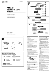
...no suministrado Cautions • This unit is designed for negative ground 12 V DC operation only. • Do not get the wires under a screw, or caught in the display. In this case, make sure that the catches on the power supply cord (...8226; Keep the release keys 5 for future use the built-in parallel. • Connect only passive speakers. 3-251-125-11 (1) FM/AM Compact Disc Player Installation/Connections Installation/Connexions Instalación/Conexiones CDX-M800 Sony Corporation © 2003 Printed in Korea 1 1 2 3 × 4 4 5 × 2 Equipment used with those in the...
...no suministrado Cautions • This unit is designed for negative ground 12 V DC operation only. • Do not get the wires under a screw, or caught in the display. In this case, make sure that the catches on the power supply cord (...8226; Keep the release keys 5 for future use the built-in parallel. • Connect only passive speakers. 3-251-125-11 (1) FM/AM Compact Disc Player Installation/Connections Installation/Connexions Instalación/Conexiones CDX-M800 Sony Corporation © 2003 Printed in Korea 1 1 2 3 × 4 4 5 × 2 Equipment used with those in the...
Product Guide / Specifications
Page 1
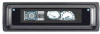
2003 SONY MOBILE PRODUCT GUIDE CDX-M800 FM/AM Compact Disc Player • (ABP) w/FL Full Motion Display • DSO, EQ7 • CD/MD...Control • 60 Degree Install • CD-R/RW Playback • 18FM + 12AM memory presets • Station Memo™, Disc Memo™, Memo List Functions • F/R Preouts w/HPF • Sub Preout w/LPF • Aux Lite Auxiliary Input ...change without notice. Design and Specifications subject to 20 kHz with wires facing viewer. Pin Number 1 2 3 4 5 6 7 8 9 10 11 12 13 14 15 16 Wire Color White Green Purple Gray Blue/white Blue Red Black White/black...
2003 SONY MOBILE PRODUCT GUIDE CDX-M800 FM/AM Compact Disc Player • (ABP) w/FL Full Motion Display • DSO, EQ7 • CD/MD...Control • 60 Degree Install • CD-R/RW Playback • 18FM + 12AM memory presets • Station Memo™, Disc Memo™, Memo List Functions • F/R Preouts w/HPF • Sub Preout w/LPF • Aux Lite Auxiliary Input ...change without notice. Design and Specifications subject to 20 kHz with wires facing viewer. Pin Number 1 2 3 4 5 6 7 8 9 10 11 12 13 14 15 16 Wire Color White Green Purple Gray Blue/white Blue Red Black White/black...
Service Manual
Page 5
CDX-M800 TABLE OF CONTENTS 1. Optical Pick-up Block 14 3. PHASE ALIGNMENT 3-1. Alignment between Arm (A-L) Assy and Arm (B-L) Assy 16 3-5. Cam (R 17 4. Block Diagram -Display Section 23 4-5. Schematic Diagram -CD Mechanism Section 25 4-7. Printed Wiring Boards -Main Section 28 4-9. ... 11 2-8. Servo Board 12 2-10. Cam (L 15 3-3. Circuit Boards Location 24 4-6. Schematic Diagram -Main Section (2/2 31 4-11. Printed Wiring Board -Display Section 34 4-14. IC Block Diagrams 36 5. CD Mechanism Section (1 43 5-6. Arm (A-L) Assy, Arm (B-L) Assy 15 3-2....
CDX-M800 TABLE OF CONTENTS 1. Optical Pick-up Block 14 3. PHASE ALIGNMENT 3-1. Alignment between Arm (A-L) Assy and Arm (B-L) Assy 16 3-5. Cam (R 17 4. Block Diagram -Display Section 23 4-5. Schematic Diagram -CD Mechanism Section 25 4-7. Printed Wiring Boards -Main Section 28 4-9. ... 11 2-8. Servo Board 12 2-10. Cam (L 15 3-3. Circuit Boards Location 24 4-6. Schematic Diagram -Main Section (2/2 31 4-11. Printed Wiring Board -Display Section 34 4-14. IC Block Diagrams 36 5. CD Mechanism Section (1 43 5-6. Arm (A-L) Assy, Arm (B-L) Assy 15 3-2....
Service Manual
Page 11
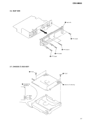
HEAT SINK 2-7. 2-6. black red white CDX-M800 5 heat sink 4 PTT 2.6x6 3 PTT 2.6x12 1 PTT 2.6x6 2 PTT 2.6x6 3 P 2x3 4 chassis (T) sub assy 11 CHASSIS (T) SUB ASSY 2 P 2x3 1 Unsolder the lead wires.
HEAT SINK 2-7. 2-6. black red white CDX-M800 5 heat sink 4 PTT 2.6x6 3 PTT 2.6x12 1 PTT 2.6x6 2 PTT 2.6x6 3 P 2x3 4 chassis (T) sub assy 11 CHASSIS (T) SUB ASSY 2 P 2x3 1 Unsolder the lead wires.
Service Manual
Page 12
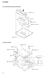
black yellow optical pick-up block 12 SERVO BOARD 6 special screws 2 Removal the solders. 8 SERVO board 7 special screw 9 FLEXIBLE board 1 CN3 4 P 2x3 5 loading motor assy 3 Unsolder the lead wires. CDX-M800 2-8. LEVER SECTION, IN SELF SW BOARD 5 guide (disc) 6 lever (R) 3 tension spring (LR) 7 lever (L) 1 special screw 2 IN SELF SW board 4 claws 2-9.
black yellow optical pick-up block 12 SERVO BOARD 6 special screws 2 Removal the solders. 8 SERVO board 7 special screw 9 FLEXIBLE board 1 CN3 4 P 2x3 5 loading motor assy 3 Unsolder the lead wires. CDX-M800 2-8. LEVER SECTION, IN SELF SW BOARD 5 guide (disc) 6 lever (R) 3 tension spring (LR) 7 lever (L) 1 special screw 2 IN SELF SW board 4 claws 2-9.
Service Manual
Page 24
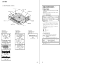
... cords. • Voltages are indicated. • Abbreviation CND : Canadian model 24 Display Board - (MODE: FM) 1 1.5Vp-p 30MHz IC2 qa (XOUT) 24 THIS NOTE IS COMMON FOR PRINTED WIRING BOARDS AND SCHEMATIC DIAGRAMS. (In addition to this, the necessary note is dc 14.4V and fed with mark...from the (Side B) pattern face are taken with part number specified. Voltage variations may be noted due to waveforms. • Signal path. CDX-M800 4-5. CIRCUIT BOARDS LOCATION IN SELF SW board SWITCH board SL SW board SERVO board LOAD SW board DISPLAY board SUB board tuner unit (TUX501)...
... cords. • Voltages are indicated. • Abbreviation CND : Canadian model 24 Display Board - (MODE: FM) 1 1.5Vp-p 30MHz IC2 qa (XOUT) 24 THIS NOTE IS COMMON FOR PRINTED WIRING BOARDS AND SCHEMATIC DIAGRAMS. (In addition to this, the necessary note is dc 14.4V and fed with mark...from the (Side B) pattern face are taken with part number specified. Voltage variations may be noted due to waveforms. • Signal path. CDX-M800 4-5. CIRCUIT BOARDS LOCATION IN SELF SW board SWITCH board SL SW board SERVO board LOAD SW board DISPLAY board SUB board tuner unit (TUX501)...
Service Manual
Page 26
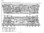
PRINTED WIRING BOARDS - CDX-M800 4-7. CD MECHANISM SECTION - • Refer to page 24 for Circuit Boards Location. 14 13 12 11 10 9 8 7 6 5 4 3 2 1 A CN2 B C D E F G H I J 26 26
PRINTED WIRING BOARDS - CDX-M800 4-7. CD MECHANISM SECTION - • Refer to page 24 for Circuit Boards Location. 14 13 12 11 10 9 8 7 6 5 4 3 2 1 A CN2 B C D E F G H I J 26 26
Service Manual
Page 28
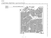
... 34) MAIN SECTION - • Refer to page 24 for Circuit Boards Location. 14 13 12 11 10 9 8 7 6 • Semiconductor Location Ref. No. Location Ref. PRINTED WIRING BOARDS - CDX-M800 4-8.
... 34) MAIN SECTION - • Refer to page 24 for Circuit Boards Location. 14 13 12 11 10 9 8 7 6 • Semiconductor Location Ref. No. Location Ref. PRINTED WIRING BOARDS - CDX-M800 4-8.
Service Manual
Page 32
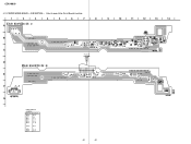
CDX-M800 4-11. SUB SECTION - • Refer to page 24 for Circuit Boards Location. 1 2 3 4 5 6 7 8 A B D512 C (Page 29) D CN501 E F CN502 G • Semiconductor Location Ref. Location D506 D507 D511 D512 D513 D514 B-10 B-6 C-8 C-8 E-13 C-10 IC503 B-13 Q503 Q504 C-9 B-10 32 32 D507 D511 R534 R532 D506 C533 9 10 11 12 13 14 Q504 R536 C539 Q503 R533 R531 D514 C540 FB503 C535 C536 C537 SW501 IC503 R538 C538 R509 D513 C535 No. PRINTED WIRING BOARD -
CDX-M800 4-11. SUB SECTION - • Refer to page 24 for Circuit Boards Location. 1 2 3 4 5 6 7 8 A B D512 C (Page 29) D CN501 E F CN502 G • Semiconductor Location Ref. Location D506 D507 D511 D512 D513 D514 B-10 B-6 C-8 C-8 E-13 C-10 IC503 B-13 Q503 Q504 C-9 B-10 32 32 D507 D511 R534 R532 D506 C533 9 10 11 12 13 14 Q504 R536 C539 Q503 R533 R531 D514 C540 FB503 C535 C536 C537 SW501 IC503 R538 C538 R509 D513 C535 No. PRINTED WIRING BOARD -
Service Manual
Page 34
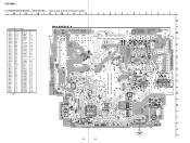
... IC1 IC2 IC62 IC301 F-2 B-1 B-4 B-10 C-8 B-6 C-2 C-7 LED901 LED902 LED903 LED905 LED906 LED908 LED909 LED911 LED912 LED913 Location F-2 H-2 H-1 F-3 F-4 H-4 A-13 H-14 H-12 H-12 Ref. No. No. PRINTED WIRING BOARD - No. Location LED957 G-4 LED958 G-13 Q903 Q904 Q905 Q907 Q908 C-11 C-10 F-4 H-2 H-2 34 34 DISPLAY SECTION - • Refer to page 24 for Circuit Boards... R922 S913 LED911 • Semiconductor Location Ref. LED915 LED916 LED917 LED919 LED920 LED921 LED922 LED931 LED955 LED956 Location F-12 F-12 F-11 H-5 H-9 H-11 F-13 A-2 F-9 F-6 Ref. CDX-M800 4-13. No.
... IC1 IC2 IC62 IC301 F-2 B-1 B-4 B-10 C-8 B-6 C-2 C-7 LED901 LED902 LED903 LED905 LED906 LED908 LED909 LED911 LED912 LED913 Location F-2 H-2 H-1 F-3 F-4 H-4 A-13 H-14 H-12 H-12 Ref. No. No. PRINTED WIRING BOARD - No. Location LED957 G-4 LED958 G-13 Q903 Q904 Q905 Q907 Q908 C-11 C-10 F-4 H-2 H-2 34 34 DISPLAY SECTION - • Refer to page 24 for Circuit Boards... R922 S913 LED911 • Semiconductor Location Ref. LED915 LED916 LED917 LED919 LED920 LED921 LED922 LED931 LED955 LED956 Location F-12 F-12 F-11 H-5 H-9 H-11 F-13 A-2 F-9 F-6 Ref. CDX-M800 4-13. No.


