XM Satellite Radio Operating manual
Page 1
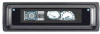
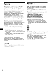
...lb. 4 oz.) Parts for the following checks, consult your nearest Sony dealer.) Introducing XMTM Satellite Radio There's a world beyond AM and FM. Except for installation and connection (1 set to change without notice....the XM Radio ID number is only equipped on the remote control. 4 Press the Disc/Preset + (Disc +) button for purchasing the Sony XM Satellite Radio Receiver. This equipment generates, uses, and ... displayed, then press the Mode button to operate this product. CDX-C8050X CDX-C800REC* CDX-M750 CDX-M650 CDX-M610 CDX-M600 MDX-C8500X XR-M550 * You may not be displayed...
...lb. 4 oz.) Parts for the following checks, consult your nearest Sony dealer.) Introducing XMTM Satellite Radio There's a world beyond AM and FM. Except for installation and connection (1 set to change without notice....the XM Radio ID number is only equipped on the remote control. 4 Press the Disc/Preset + (Disc +) button for purchasing the Sony XM Satellite Radio Receiver. This equipment generates, uses, and ... displayed, then press the Mode button to operate this product. CDX-C8050X CDX-C800REC* CDX-M750 CDX-M650 CDX-M610 CDX-M600 MDX-C8500X XR-M550 * You may not be displayed...
XM Satellite Radio Operating manual
Page 2
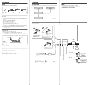
...be damaged by the screws or the unit itself. • Be sure to rain or moisture. - Warning Use a fuse with the tapping screws. POWER SONY BUS CONTROL OUT IN AUDIO L OUT R L IN R ANTENNA TER SAT 2 Connect as the connector hook facing down Green Yellow (Curry) XM antenna (not ...internal malfunction. The unit is not exposed to direct sunlight. - Connection Connection example XM Antenna* XT-XM1 CD/MD changer* Connection diagram Sony BUS Compatible Car Audio* Cautions • This unit is not subject to damage the fuel tank or brake line with the specified amperage...
...be damaged by the screws or the unit itself. • Be sure to rain or moisture. - Warning Use a fuse with the tapping screws. POWER SONY BUS CONTROL OUT IN AUDIO L OUT R L IN R ANTENNA TER SAT 2 Connect as the connector hook facing down Green Yellow (Curry) XM antenna (not ...internal malfunction. The unit is not exposed to direct sunlight. - Connection Connection example XM Antenna* XT-XM1 CD/MD changer* Connection diagram Sony BUS Compatible Car Audio* Cautions • This unit is not subject to damage the fuel tank or brake line with the specified amperage...
Installation/Connection Instructions
Page 1
...First connect the black ground lead, then connect the yellow and red power input leads. 2 To the power antenna control lead or power supply lead of the right speakers with this unit. If the catches are keyed to those of ... each component's fuse. • When no suministrado Cautions • This unit is designed for amplifiers. 3-251-125-11 (1) FM/AM Compact Disc Player Installation/Connections Installation/Connexions Instalación/Conexiones CDX-M800 Sony Corporation © 2003 Printed in Korea 1 1 2 3 × 4 4 5 × 2 Equipment used with those ...
...First connect the black ground lead, then connect the yellow and red power input leads. 2 To the power antenna control lead or power supply lead of the right speakers with this unit. If the catches are keyed to those of ... each component's fuse. • When no suministrado Cautions • This unit is designed for amplifiers. 3-251-125-11 (1) FM/AM Compact Disc Player Installation/Connections Installation/Connexions Instalación/Conexiones CDX-M800 Sony Corporation © 2003 Printed in Korea 1 1 2 3 × 4 4 5 × 2 Equipment used with those ...
Operating Instructions
Page 2
... RM-X110 • Optional controller accessory Wireless rotary commander RM-X6S *1 This unit works with Sony products only. *2 A CD TEXT disc is encouraged to try to correct the interference by turning the equipment off and on a circuit different from that to radio communications. These limits are cautioned that this Sony Compact Disc Player. Connect the equipment into...
... RM-X110 • Optional controller accessory Wireless rotary commander RM-X6S *1 This unit works with Sony products only. *2 A CD TEXT disc is encouraged to try to correct the interference by turning the equipment off and on a circuit different from that to radio communications. These limits are cautioned that this Sony Compact Disc Player. Connect the equipment into...
Operating Instructions
Page 3
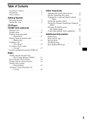
...-up 16 Other Functions Adjusting the sound characteristics 16 Quickly attenuating the sound 17 Changing the sound and display settings - Disc Memo 12 Locating a disc by name - Shuffle Play 11 Labeling a CD - Best Tuning Memory (BTM 13 Receiving the stored stations 14 Storing... names - Repeat Play 11 Playing tracks in a station through a list - Table of Contents Location of controls 4 Precautions 6 Notes on discs 7 Getting Started Resetting the unit 8 Setting the clock 8 CD Player CD/MD Unit (optional) Playing a disc 9 Display items 10 Playing tracks repeatedly -
...-up 16 Other Functions Adjusting the sound characteristics 16 Quickly attenuating the sound 17 Changing the sound and display settings - Disc Memo 12 Locating a disc by name - Shuffle Play 11 Labeling a CD - Best Tuning Memory (BTM 13 Receiving the stored stations 14 Storing... names - Repeat Play 11 Playing tracks in a station through a list - Table of Contents Location of controls 4 Precautions 6 Notes on discs 7 Getting Started Resetting the unit 8 Setting the clock 8 CD Player CD/MD Unit (optional) Playing a disc 9 Display items 10 Playing tracks repeatedly -
Operating Instructions
Page 4
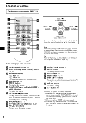
SEEK+ ENTER OFF + ATT VOL - f SOURCE (Power on/Radio/CD/MD*1/ AUX*2) button To select the source. SOUND SOURCE DISC - a SCRL (scroll) button 10 b DSPL (display mode change) button 10, 12 c Number buttons (1) REP 11 (2) SHUF 11 To store stations/receive stored stations. g SEEK ( d EQ7 button 18 e MENU button To display the menus. Refer to the pages listed for details. Location of controls Card remote commander RM-X110 SCRL DSPL REP 1 4 EQ7 OPEN/CLOSE SHUF 2 5 MODE 3 6 DSO MENU DISC + LIST SEEK-
SEEK+ ENTER OFF + ATT VOL - f SOURCE (Power on/Radio/CD/MD*1/ AUX*2) button To select the source. SOUND SOURCE DISC - a SCRL (scroll) button 10 b DSPL (display mode change) button 10, 12 c Number buttons (1) REP 11 (2) SHUF 11 To store stations/receive stored stations. g SEEK ( d EQ7 button 18 e MENU button To display the menus. Refer to the pages listed for details. Location of controls Card remote commander RM-X110 SCRL DSPL REP 1 4 EQ7 OPEN/CLOSE SHUF 2 5 MODE 3 6 DSO MENU DISC + LIST SEEK-
Operating Instructions
Page 9
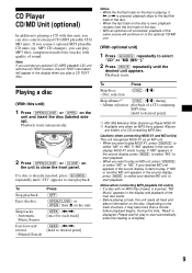
... TEXT information will appear in the display when you play MP3 files; If a disc is already inserted, press (SOURCE) repeatedly until "CD" appears to close the front panel. Automatic Music Sensor Fast-forward/ reverse - CD Player CD/MD Unit (optional) In addition to playing a CD with this unit)... - If you connect optional MP3 playable CD units (eg., MP3 CD changer), you can also control external CD (MP3 playable CD)/ MD units. Playing a disc (With this unit, you can play a CD TEXT disc. Playback starts automatically. 2 Press (OPEN/CLOSE) or (CLOSE) on the unit to start playback...
... TEXT information will appear in the display when you play MP3 files; If a disc is already inserted, press (SOURCE) repeatedly until "CD" appears to close the front panel. Automatic Music Sensor Fast-forward/ reverse - CD Player CD/MD Unit (optional) In addition to playing a CD with this unit)... - If you connect optional MP3 playable CD units (eg., MP3 CD changer), you can also control external CD (MP3 playable CD)/ MD units. Playing a disc (With this unit, you can play a CD TEXT disc. Playback starts automatically. 2 Press (OPEN/CLOSE) or (CLOSE) on the unit to start playback...

Operating Instructions
Page 11
...repeatedly until the desired setting appears in the display. Playing tracks repeatedly - Repeat Play starts. To return to normal play the tracks on the current disc in the display. Note "SHUF-All" will not shuffle tracks between CD units and MD units. 11 to repeat the current track. • ... Play You can select: • SHUF-Album*1 - to play the albums in the current optional CD unit with the MP3 file control function in the current disc. *1 Available only when an MP3 file is played. *2 Available only when one or more optional CD (MD) units are connected. *3 Available only ...
...repeatedly until the desired setting appears in the display. Playing tracks repeatedly - Repeat Play starts. To return to normal play the tracks on the current disc in the display. Note "SHUF-All" will not shuffle tracks between CD units and MD units. 11 to repeat the current track. • ... Play You can select: • SHUF-Album*1 - to play the albums in the current optional CD unit with the MP3 file control function in the current disc. *1 Available only when an MP3 file is played. *2 Available only when one or more optional CD (MD) units are connected. *3 Available only ...
Operating Instructions
Page 23
...discs) CDX-T70MX, CDX-T69 MD changer (6 discs) MDX-66XLP MG-MS System-up Player MGS-X1 XM Satellite Radio Receiver XT-XM1 Source selector XA-C30 AUX-IN Selector XA-300 Note This unit cannot be connected to a digital preamplifier or an equalizer which is Sony BUS system compatible. CD Player... (mono) Power antenna relay control terminal Power amplifier control terminal Telephone ATT control terminal Illumination control terminal BUS control input terminal BUS audio input or AUX IN terminal Antenna input terminal Tone controls Loudness Power requirements Dimensions Mounting dimensions...
...discs) CDX-T70MX, CDX-T69 MD changer (6 discs) MDX-66XLP MG-MS System-up Player MGS-X1 XM Satellite Radio Receiver XT-XM1 Source selector XA-C30 AUX-IN Selector XA-300 Note This unit cannot be connected to a digital preamplifier or an equalizer which is Sony BUS system compatible. CD Player... (mono) Power antenna relay control terminal Power amplifier control terminal Telephone ATT control terminal Illumination control terminal BUS control input terminal BUS audio input or AUX IN terminal Antenna input terminal Tone controls Loudness Power requirements Dimensions Mounting dimensions...
Operating Instructions
Page 24
... (VOL) (+) to adjust the volume. • Cancel the ATT function. • Set the fader control to on. The fuse has blown. The leads are not matched correctly with your car has a built-in FM/ AM antenna in a sturdy part of the car antenna. • The auto antenna will not go...• The power connecting cord is forcibly inserted upside down or in amplifier. t Press (SOURCE) (or insert a disc) to turn on , the sound is sometimes hampered by noises. • Connect a power antenna control lead (blue) or accessory power supply lead (red) to the power supply lead of the power antenna...
... (VOL) (+) to adjust the volume. • Cancel the ATT function. • Set the fader control to on. The fuse has blown. The leads are not matched correctly with your car has a built-in FM/ AM antenna in a sturdy part of the car antenna. • The auto antenna will not go...• The power connecting cord is forcibly inserted upside down or in amplifier. t Press (SOURCE) (or insert a disc) to turn on , the sound is sometimes hampered by noises. • Connect a power antenna control lead (blue) or accessory power supply lead (red) to the power supply lead of the power antenna...
Product Guide / Specifications
Page 1
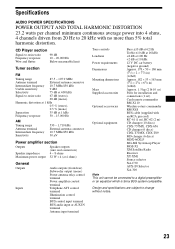
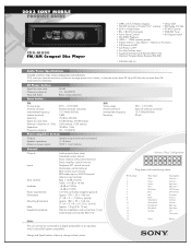
... 12345678 9 10 11 12 13 14 15 16 Plug shown with no more than 5% total harmonic distortion. 2003 SONY MOBILE PRODUCT GUIDE CDX-M800 FM/AM Compact Disc Player • (ABP) w/FL Full Motion Display • DSO, EQ7 • CD/MD Control w/Custom File™ memory • XM Ready, CD Text • 52W x 4 High Power • XT-XM1...
... 12345678 9 10 11 12 13 14 15 16 Plug shown with no more than 5% total harmonic distortion. 2003 SONY MOBILE PRODUCT GUIDE CDX-M800 FM/AM Compact Disc Player • (ABP) w/FL Full Motion Display • DSO, EQ7 • CD/MD Control w/Custom File™ memory • XM Ready, CD Text • 52W x 4 High Power • XT-XM1...
Product Guide / Specifications
Page 2
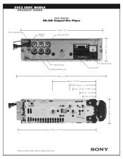
2003 SONY MOBILE PRODUCT GUIDE CDX-M800 FM/AM Compact Disc Player From car antenna SUB OUT (mono) 178 mm (7”) Audio OUT Front 50 mm (2”) Audio OUT Rear BUS Audio IN/Aux IN BUS Control IN Fuse (10A) 186 mm (7 3/8”) 88 mm (3 7/16”) 53 mm ( 2 1/16”) 47 mm (1 7/8”) 33 mm (1 5/16”) 27 mm (1 1/16”) 50 mm (2”) 163 mm (6 1/2”) Design and Specifications subject to change without notice.
2003 SONY MOBILE PRODUCT GUIDE CDX-M800 FM/AM Compact Disc Player From car antenna SUB OUT (mono) 178 mm (7”) Audio OUT Front 50 mm (2”) Audio OUT Rear BUS Audio IN/Aux IN BUS Control IN Fuse (10A) 186 mm (7 3/8”) 88 mm (3 7/16”) 53 mm ( 2 1/16”) 47 mm (1 7/8”) 33 mm (1 5/16”) 27 mm (1 1/16”) 50 mm (2”) 163 mm (6 1/2”) Design and Specifications subject to change without notice.
Service Manual
Page 2
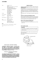
CDX-M800 Inputs Tone controls Loudness Power requirements Dimensions Mounting dimensions Mass Supplied accessories Telephone ATT control terminal Illumination control terminal (US, Canadian model) BUS control input terminal BUS audio input or AUX IN terminal Antenna input terminal (US, Canadian model) Aerial input terminal...-up block SAFETY-RELATED COMPONENT WARNING!! REPLACE THESE COMPONENTS WITH SONY PARTS WHOSE PART NUMBERS APPEAR AS SHOWN IN THIS MANUAL OR IN SUPPLEMENTS PUBLISHED BY SONY. Notes on the disc reflective surface by heat. Design and specifications are subject to ...
CDX-M800 Inputs Tone controls Loudness Power requirements Dimensions Mounting dimensions Mass Supplied accessories Telephone ATT control terminal Illumination control terminal (US, Canadian model) BUS control input terminal BUS audio input or AUX IN terminal Antenna input terminal (US, Canadian model) Aerial input terminal...-up block SAFETY-RELATED COMPONENT WARNING!! REPLACE THESE COMPONENTS WITH SONY PARTS WHOSE PART NUMBERS APPEAR AS SHOWN IN THIS MANUAL OR IN SUPPLEMENTS PUBLISHED BY SONY. Notes on the disc reflective surface by heat. Design and specifications are subject to ...
Service Manual
Page 5
... -Main Section 28 4-9. CD Mechanism Section (3 45 6. GENERAL Location of Controls 6 Connection example (US, Canadian Model 6 Connections (US, Canadian Model 7 2. Cam (R 17 4. EXPLODED VIEWS 5-1. Main Board 10 2-6. Motor Block 16 3-4. DIAGRAMS 4-1. Front Panel Section 42 5-5. CD Mechanism Section (2 44 5-7. PHASE ALIGNMENT 3-1. CDX-M800 TABLE OF CONTENTS 1. Printed Wiring Boards -CD Mechanism Section 26...
... -Main Section 28 4-9. CD Mechanism Section (3 45 6. GENERAL Location of Controls 6 Connection example (US, Canadian Model 6 Connections (US, Canadian Model 7 2. Cam (R 17 4. EXPLODED VIEWS 5-1. Main Board 10 2-6. Motor Block 16 3-4. DIAGRAMS 4-1. Front Panel Section 42 5-5. CD Mechanism Section (2 44 5-7. PHASE ALIGNMENT 3-1. CDX-M800 TABLE OF CONTENTS 1. Printed Wiring Boards -CD Mechanism Section 26...
Service Manual
Page 6
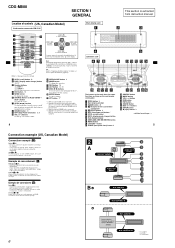
g SEEK ( CDX-M800 SECTION 1 GENERAL This section is extracted from instruction manual. Location of controls (US, Canadian Model) Card remote commander RM-X110 SCRL DSPL REP 1 4 EQ7 OPEN/CLOSE SHUF 2 5 MODE 3 6 DSO MENU DISC + LIST SEEK- SOUND SOURCE DISC - SEEK+ ENTER OFF + AT T VOL - a SCRL (scroll) button 10 b DSPL (display mode change) button 10, 12 c Number...
g SEEK ( CDX-M800 SECTION 1 GENERAL This section is extracted from instruction manual. Location of controls (US, Canadian Model) Card remote commander RM-X110 SCRL DSPL REP 1 4 EQ7 OPEN/CLOSE SHUF 2 5 MODE 3 6 DSO MENU DISC + LIST SEEK- SOUND SOURCE DISC - SEEK+ ENTER OFF + AT T VOL - a SCRL (scroll) button 10 b DSPL (display mode change) button 10, 12 c Number...
Service Manual
Page 19
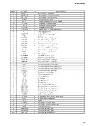
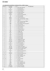
...data output O Display CPU BUS clock output CDX-M800 19 Power supply pin (+5V) O Display CPU reset signal output - Ground O Display CPU chip enable output - Power supply pin (+5V) I CD servo RFOK signal input O CD servo crystal OSC control signal output - A/D converter reference voltage (+...signal input I Front panel open detect signal input I Front panel current detect signal input O Front panel open/close control signal output O Front panel open/close control signal output I ROM correction enable signal input I Tuner noise detect signal input I Tuner multi-path signal input I...
...data output O Display CPU BUS clock output CDX-M800 19 Power supply pin (+5V) O Display CPU reset signal output - Ground O Display CPU chip enable output - Power supply pin (+5V) I CD servo RFOK signal input O CD servo crystal OSC control signal output - A/D converter reference voltage (+...signal input I Front panel open detect signal input I Front panel current detect signal input O Front panel open/close control signal output O Front panel open/close control signal output I ROM correction enable signal input I Tuner noise detect signal input I Tuner multi-path signal input I...
Service Manual
Page 20
... . (Open) 99 FL DATA2 O FL serial data output 100 FL CLK IN I Main clock signal input (30MHz) 14 VCC - Power supply pin (+5V) 98 RXD1 - CDX-M800 • IC2 M30833FJGP-066 (DISPLAY SYSTEM CONTROL) (DISPLAY Board) Pin No.
... . (Open) 99 FL DATA2 O FL serial data output 100 FL CLK IN I Main clock signal input (30MHz) 14 VCC - Power supply pin (+5V) 98 RXD1 - CDX-M800 • IC2 M30833FJGP-066 (DISPLAY SYSTEM CONTROL) (DISPLAY Board) Pin No.
Service Manual
Page 21
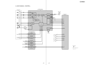
... 16 ROUT 12 PACK 52 TSTB 56 TSCK 55 TSI 54 SI 8 SO 7 SCK 6 STB 5 AO 4 RST 3 RFOK 2 R-CH (Page 22) TUNER SECTION A CDL SYSTEM CONTROL IC303 (1/3) 3 CD TSO 4 CD TSI 5 CD TCKO 57 CD TSTB 55 CD A0 54 CD RST 58 CD RFOK XTALEN OSC 9 23 24 X1 16....9344MHz SW5 (DOWN) SW2 (SELF) SW3 (DISC IN) SW4 (LIMIT) 59 CD XTAL EN 46 CD D SW 72 CD SELF SW 48 CD IN SW 45 CD LIMIT 52 CD LM LO 53 CD LM EJ CDX-M800 • Signal path :CD • R-ch is omitted due to same...
... 16 ROUT 12 PACK 52 TSTB 56 TSCK 55 TSI 54 SI 8 SO 7 SCK 6 STB 5 AO 4 RST 3 RFOK 2 R-CH (Page 22) TUNER SECTION A CDL SYSTEM CONTROL IC303 (1/3) 3 CD TSO 4 CD TSI 5 CD TCKO 57 CD TSTB 55 CD A0 54 CD RST 58 CD RFOK XTALEN OSC 9 23 24 X1 16....9344MHz SW5 (DOWN) SW2 (SELF) SW3 (DISC IN) SW4 (LIMIT) 59 CD XTAL EN 46 CD D SW 72 CD SELF SW 48 CD IN SW 45 CD LIMIT 52 CD LM LO 53 CD LM EJ CDX-M800 • Signal path :CD • R-ch is omitted due to same...
Service Manual
Page 22
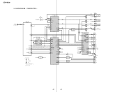
CDX-M800 4-3. AU +8V +5V REG Q501 TU+5V ELECTRONIC VOLUME IC401 4 PDL 42 MDL 32 AC OUT L 31 AC IN L 40 AML 12 SDA 13 SCL 15 MUTE LF 25 OUT LR 24 OUT SW 17 SA CLK 14 SA OUT 16 SYSTEM CONTROL IC303 (2/3) 26 VOL ATT 28 I2C SIO 27 I2C...) TUNER UNIT TUX501 1 ANT L4 R3 CD SECTION (Page 21) A CDL AM SDA 14 SCL 13 RDS 9 QUALITY 5 AEP,UK,E MODEL RDS DECODER IC502 16 FM DET 4 OSCD SDA 9 SCL 10 5 OSCI X501 4.3MHz DAVN 8 TU MUTE 7 MUTE CONDITION 8 S-METER 6 SDA 17 EEPROM SCL 16 • Signal path...
CDX-M800 4-3. AU +8V +5V REG Q501 TU+5V ELECTRONIC VOLUME IC401 4 PDL 42 MDL 32 AC OUT L 31 AC IN L 40 AML 12 SDA 13 SCL 15 MUTE LF 25 OUT LR 24 OUT SW 17 SA CLK 14 SA OUT 16 SYSTEM CONTROL IC303 (2/3) 26 VOL ATT 28 I2C SIO 27 I2C...) TUNER UNIT TUX501 1 ANT L4 R3 CD SECTION (Page 21) A CDL AM SDA 14 SCL 13 RDS 9 QUALITY 5 AEP,UK,E MODEL RDS DECODER IC502 16 FM DET 4 OSCD SDA 9 SCL 10 5 OSCI X501 4.3MHz DAVN 8 TU MUTE 7 MUTE CONDITION 8 S-METER 6 SDA 17 EEPROM SCL 16 • Signal path...
Service Manual
Page 23
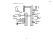
... COM1 I COM8 LED SW1 105 INH 117 CF 118 CLK 119 DATA 120 DIMMER 104 106 LED CONTROL LED SW2 Q903,904 DIMMER CONTROL Q905 FL 900 3 BATT 10 CHECK X301 30MHz SUB SYSTEM CONTROL IC2 11 XOUT 13 XIN 37 LCD INH 36 LCD CE 35 FL CLK 33 FL DAT1 SYS... 1 MOTOR+B REG IC306 3 2 MT+B MOTOR 11 DRIVE 6 IC307 12 VREF CONTROL Q306,307 M601 (OPEN/CLOSE9 3 14 16 FP CTRL 2 I-DET 76 OPEN SW 75 CLOSE SW 74 I-DET Q305 7 I-DET 3 IC308 SW900 (OPEN/CLOSE) LED CONTROL Q503,504 D512 (DISC IN) OPEN KEY 90 S931 (OPEN) CDX-M800 23 23 DISPLAY SECTION - BLOCK DIAGRAM - 4-4.
... COM1 I COM8 LED SW1 105 INH 117 CF 118 CLK 119 DATA 120 DIMMER 104 106 LED CONTROL LED SW2 Q903,904 DIMMER CONTROL Q905 FL 900 3 BATT 10 CHECK X301 30MHz SUB SYSTEM CONTROL IC2 11 XOUT 13 XIN 37 LCD INH 36 LCD CE 35 FL CLK 33 FL DAT1 SYS... 1 MOTOR+B REG IC306 3 2 MT+B MOTOR 11 DRIVE 6 IC307 12 VREF CONTROL Q306,307 M601 (OPEN/CLOSE9 3 14 16 FP CTRL 2 I-DET 76 OPEN SW 75 CLOSE SW 74 I-DET Q305 7 I-DET 3 IC308 SW900 (OPEN/CLOSE) LED CONTROL Q503,504 D512 (DISC IN) OPEN KEY 90 S931 (OPEN) CDX-M800 23 23 DISPLAY SECTION - BLOCK DIAGRAM - 4-4.


