XM Satellite Radio Operating manual
Page 2
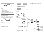
...location carefully, observing the following: - Black RCA pin cord (not supplied) BUS cable (not supplied) 4 3 OUT OUT IN CD/MD changer (not supplied) Sony BUS Compatible Car Audio (not supplied) IN Note When you are keyed to excessive vibration. - The unit is not subject to direct sunlight or hot... sources (such as in a car parked in or under the trunk should not be used because of a higher amperage fuse may be no wire harnesses or pipes under the floor carpet, where the heat dissipation from the unit will not be exposed to temperatures exceeding 55°C (131&#...
...location carefully, observing the following: - Black RCA pin cord (not supplied) BUS cable (not supplied) 4 3 OUT OUT IN CD/MD changer (not supplied) Sony BUS Compatible Car Audio (not supplied) IN Note When you are keyed to excessive vibration. - The unit is not subject to direct sunlight or hot... sources (such as in a car parked in or under the trunk should not be used because of a higher amperage fuse may be no wire harnesses or pipes under the floor carpet, where the heat dissipation from the unit will not be exposed to temperatures exceeding 55°C (131&#...
Installation/Connection Instructions
Page 1
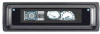
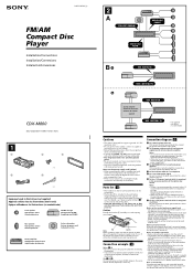
... when the ignition key is energized at all times. Note on the tuner. • When your car. 3-251-125-11 (1) FM/AM Compact Disc Player Installation/Connections Installation/Connexions Instalación/Conexiones CDX-M800 Sony Corporation © 2003 Printed in Korea 1 1 2 3 × 4 4 5 × 2 Equipment used with this unit....For details, see "Notes on both sides of the ignition key switch Notes • If there is energized at all ground wires to a common ground point. • Be sure to connect the ground cord before shipping. If the catches are bent inwards ...
... when the ignition key is energized at all times. Note on the tuner. • When your car. 3-251-125-11 (1) FM/AM Compact Disc Player Installation/Connections Installation/Connexions Instalación/Conexiones CDX-M800 Sony Corporation © 2003 Printed in Korea 1 1 2 3 × 4 4 5 × 2 Equipment used with this unit....For details, see "Notes on both sides of the ignition key switch Notes • If there is energized at all ground wires to a common ground point. • Be sure to connect the ground cord before shipping. If the catches are bent inwards ...
Product Guide / Specifications
Page 1
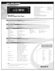
...and flutter 90 dB 10 – 20,000 Hz Below measurable limit Tuner Section FM Tuning range Antenna terminal Intermediate frequency Usable sensitivity Selectivity Signal-to change without notice. 2003 SONY MOBILE PRODUCT GUIDE CDX-M800 FM/AM Compact Disc Player • (ABP) w/FL Full Motion Display • DSO, EQ7 •...ohms, 4 channels driven from 20 Hz to a digital preamplifier or an equalizer which is Sony BUS system compatible. Pin Number 1 2 3 4 5 6 7 8 9 10 11 12 13 14 15 16 Wire Color White Green Purple Gray Blue/white Blue Red Black White/black Green/black Purple/black ...
...and flutter 90 dB 10 – 20,000 Hz Below measurable limit Tuner Section FM Tuning range Antenna terminal Intermediate frequency Usable sensitivity Selectivity Signal-to change without notice. 2003 SONY MOBILE PRODUCT GUIDE CDX-M800 FM/AM Compact Disc Player • (ABP) w/FL Full Motion Display • DSO, EQ7 •...ohms, 4 channels driven from 20 Hz to a digital preamplifier or an equalizer which is Sony BUS system compatible. Pin Number 1 2 3 4 5 6 7 8 9 10 11 12 13 14 15 16 Wire Color White Green Purple Gray Blue/white Blue Red Black White/black Green/black Purple/black ...
Service Manual
Page 5
CDX-M800 TABLE OF CONTENTS 1. Heat Sink 11 2-7. Lever Section, ...Assy 10 2-5. Main Board 10 2-6. Floating Block Assy 13 2-12. Schematic Diagram -Main Section (1/2 30 4-10. Printed Wiring Board -Sub Section 32 4-12. Schematic Diagram -Display Section 35 4-15. Main Board Section 41 5-4. Front Panel Assy ...Cam (L 15 3-3. DIAGRAMS 4-1. Schematic Diagram -Main Section (2/2 31 4-11. Schematic Diagram -Sub Section 33 4-13. Printed Wiring Board -Display Section 34 4-14. Cam Section 40 5-3. GENERAL Location of Controls 6 Connection example (US, Canadian Model 6 ...
CDX-M800 TABLE OF CONTENTS 1. Heat Sink 11 2-7. Lever Section, ...Assy 10 2-5. Main Board 10 2-6. Floating Block Assy 13 2-12. Schematic Diagram -Main Section (1/2 30 4-10. Printed Wiring Board -Sub Section 32 4-12. Schematic Diagram -Display Section 35 4-15. Main Board Section 41 5-4. Front Panel Assy ...Cam (L 15 3-3. DIAGRAMS 4-1. Schematic Diagram -Main Section (2/2 31 4-11. Schematic Diagram -Sub Section 33 4-13. Printed Wiring Board -Display Section 34 4-14. Cam Section 40 5-3. GENERAL Location of Controls 6 Connection example (US, Canadian Model 6 ...
Service Manual
Page 11
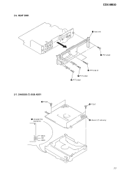
CHASSIS (T) SUB ASSY 2 P 2x3 1 Unsolder the lead wires. black red white CDX-M800 5 heat sink 4 PTT 2.6x6 3 PTT 2.6x12 1 PTT 2.6x6 2 PTT 2.6x6 3 P 2x3 4 chassis (T) sub assy 11 2-6. HEAT SINK 2-7.
CHASSIS (T) SUB ASSY 2 P 2x3 1 Unsolder the lead wires. black red white CDX-M800 5 heat sink 4 PTT 2.6x6 3 PTT 2.6x12 1 PTT 2.6x6 2 PTT 2.6x6 3 P 2x3 4 chassis (T) sub assy 11 2-6. HEAT SINK 2-7.
Service Manual
Page 12
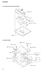
LEVER SECTION, IN SELF SW BOARD 5 guide (disc) 6 lever (R) 3 tension spring (LR) 7 lever (L) 1 special screw 2 IN SELF SW board 4 claws 2-9. black yellow optical pick-up block 12 SERVO BOARD 6 special screws 2 Removal the solders. 8 SERVO board 7 special screw 9 FLEXIBLE board 1 CN3 4 P 2x3 5 loading motor assy 3 Unsolder the lead wires. CDX-M800 2-8.
LEVER SECTION, IN SELF SW BOARD 5 guide (disc) 6 lever (R) 3 tension spring (LR) 7 lever (L) 1 special screw 2 IN SELF SW board 4 claws 2-9. black yellow optical pick-up block 12 SERVO BOARD 6 special screws 2 Removal the solders. 8 SERVO board 7 special screw 9 FLEXIBLE board 1 CN3 4 P 2x3 5 loading motor assy 3 Unsolder the lead wires. CDX-M800 2-8.
Service Manual
Page 24
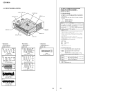
...tolerances. • Circled numbers refer to normal production tolerances. • Waveforms are taken with a VOM (Input impedance 10 MΩ). CDX-M800 4-5. Replace only with mark 0 are taken with a oscilloscope. Note: The components identified by mark 0 or dotted line with part.... Note: Les composants identifiés par une marque 0 sont critiques pour la sécurité. F : FM f : AM/MW/LW J : CD • Abbreviation CND : Canadian model for printed wiring boards: • X : parts extracted from the component side. • Y : parts extracted from the conductor...
...tolerances. • Circled numbers refer to normal production tolerances. • Waveforms are taken with a VOM (Input impedance 10 MΩ). CDX-M800 4-5. Replace only with mark 0 are taken with a oscilloscope. Note: The components identified by mark 0 or dotted line with part.... Note: Les composants identifiés par une marque 0 sont critiques pour la sécurité. F : FM f : AM/MW/LW J : CD • Abbreviation CND : Canadian model for printed wiring boards: • X : parts extracted from the component side. • Y : parts extracted from the conductor...
Service Manual
Page 26
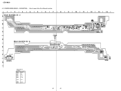
CDX-M800 4-7. CD MECHANISM SECTION - • Refer to page 24 for Circuit Boards Location. 14 13 12 11 10 9 8 7 6 5 4 3 2 1 A CN2 B C D E F G H I J 26 26 PRINTED WIRING BOARDS -
CDX-M800 4-7. CD MECHANISM SECTION - • Refer to page 24 for Circuit Boards Location. 14 13 12 11 10 9 8 7 6 5 4 3 2 1 A CN2 B C D E F G H I J 26 26 PRINTED WIRING BOARDS -
Service Manual
Page 28
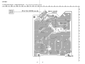
Location Ref. PRINTED WIRING BOARDS - CDX-M800 4-8. No. MAIN SECTION - • Refer to page 24 for Circuit Boards Location. 14 13 12 11 10 9 8 7 6 • Semiconductor Location Ref. No. (D101) (D102) (D103) (...
Location Ref. PRINTED WIRING BOARDS - CDX-M800 4-8. No. MAIN SECTION - • Refer to page 24 for Circuit Boards Location. 14 13 12 11 10 9 8 7 6 • Semiconductor Location Ref. No. (D101) (D102) (D103) (...
Service Manual
Page 32
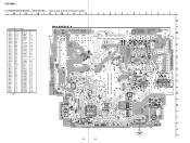
SUB SECTION - • Refer to page 24 for Circuit Boards Location. 1 2 3 4 5 6 7 8 A B D512 C (Page 29) D CN501 E F CN502 G • Semiconductor Location Ref. PRINTED WIRING BOARD - Location D506 D507 D511 D512 D513 D514 B-10 B-6 C-8 C-8 E-13 C-10 IC503 B-13 Q503 Q504 C-9 B-10 32 32 D507 D511 R534 R532 D506 C533 9 10 11 12 13 14 Q504 R536 C539 Q503 R533 R531 D514 C540 FB503 C535 C536 C537 SW501 IC503 R538 C538 R509 D513 C535 CDX-M800 4-11. No.
SUB SECTION - • Refer to page 24 for Circuit Boards Location. 1 2 3 4 5 6 7 8 A B D512 C (Page 29) D CN501 E F CN502 G • Semiconductor Location Ref. PRINTED WIRING BOARD - Location D506 D507 D511 D512 D513 D514 B-10 B-6 C-8 C-8 E-13 C-10 IC503 B-13 Q503 Q504 C-9 B-10 32 32 D507 D511 R534 R532 D506 C533 9 10 11 12 13 14 Q504 R536 C539 Q503 R533 R531 D514 C540 FB503 C535 C536 C537 SW501 IC503 R538 C538 R509 D513 C535 CDX-M800 4-11. No.
Service Manual
Page 34
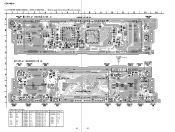
... LED931 LED955 LED956 Location F-12 F-12 F-11 H-5 H-9 H-11 F-13 A-2 F-9 F-6 Ref. Location LED957 G-4 LED958 G-13 Q903 Q904 Q905 Q907 Q908 C-11 C-10 F-4 H-2 H-2 34 34 No. CDX-M800 4-13. PRINTED WIRING BOARD - No. No. DISPLAY SECTION - • Refer to page 24 for Circuit Boards Location. 1 2 3 4 5 6 7 A C905 R988 LED931 B S931 D901 C914 C904 IC62 C903 R969...
... LED931 LED955 LED956 Location F-12 F-12 F-11 H-5 H-9 H-11 F-13 A-2 F-9 F-6 Ref. Location LED957 G-4 LED958 G-13 Q903 Q904 Q905 Q907 Q908 C-11 C-10 F-4 H-2 H-2 34 34 No. CDX-M800 4-13. PRINTED WIRING BOARD - No. No. DISPLAY SECTION - • Refer to page 24 for Circuit Boards Location. 1 2 3 4 5 6 7 A C905 R988 LED931 B S931 D901 C914 C904 IC62 C903 R969...


