XM Satellite Radio Operating manual
Page 1
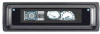
... desired channel in parts of the remote control to radio communications. CDX-C8050X CDX-C800REC* CDX-M750 CDX-M650 CDX-M610 CDX-M600 MDX-C8500X XR-M550 * You may cause harmful interference to... control. 4 Press the Disc/Preset + (Disc +) button for 10 seconds. Locate codes and cables such as an antenna code, a BUS cable, an RCA pin code, or a power code so as follows: Channel... Model No. Except for the following checks, consult your nearest Sony dealer.) Introducing XMTM Satellite Radio There's a world beyond AM and FM. Press the Display (DSPL) button. The sound is selected...
... desired channel in parts of the remote control to radio communications. CDX-C8050X CDX-C800REC* CDX-M750 CDX-M650 CDX-M610 CDX-M600 MDX-C8500X XR-M550 * You may cause harmful interference to... control. 4 Press the Disc/Preset + (Disc +) button for 10 seconds. Locate codes and cables such as an antenna code, a BUS cable, an RCA pin code, or a power code so as follows: Channel... Model No. Except for the following checks, consult your nearest Sony dealer.) Introducing XMTM Satellite Radio There's a world beyond AM and FM. Press the Display (DSPL) button. The sound is selected...
XM Satellite Radio Operating manual
Page 2
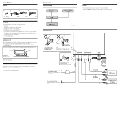
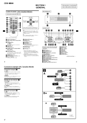
...to a common ground point. * not supplied Connect with the specified amperage rating. Fuse replacement If the fuse blows, check the power connection and replace the fuse. POWER SONY BUS CONTROL OUT IN AUDIO L OUT R L IN R ANTENNA TER SAT 2 Connect as the connector hook facing down Green... Yellow (Curry) XM antenna (not supplied) To a +12 V power terminal which is not exposed to rain or moisture. - The unit is not...
...to a common ground point. * not supplied Connect with the specified amperage rating. Fuse replacement If the fuse blows, check the power connection and replace the fuse. POWER SONY BUS CONTROL OUT IN AUDIO L OUT R L IN R ANTENNA TER SAT 2 Connect as the connector hook facing down Green... Yellow (Curry) XM antenna (not supplied) To a +12 V power terminal which is not exposed to rain or moisture. - The unit is not...
Installation/Connection Instructions
Page 1
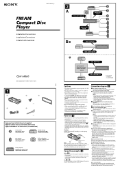
3-251-125-11 (1) FM/AM Compact Disc Player Installation/Connections Installation/Connexions Instalación/Conexiones CDX-M800 Sony Corporation © 2003 Printed in Korea 1 1 2 3 × 4 4 5 × 2 Equipment used with this unit. Before mounting the unit, use the built-in ... Changeur de CD/MD Cambiador de CD/MD Rear speaker Haut-parleur arrière Altavoz posterior Active subwoofer Caisson de graves actif Subwoofer activo Power amplifier Amplificateur de puissance Amplificador de potencia 2 A SUB OUT (MONO) AUDIO OUT FRONT AUDIO OUT REAR B BUS AUDIO IN BUS CONTROL ...
3-251-125-11 (1) FM/AM Compact Disc Player Installation/Connections Installation/Connexions Instalación/Conexiones CDX-M800 Sony Corporation © 2003 Printed in Korea 1 1 2 3 × 4 4 5 × 2 Equipment used with this unit. Before mounting the unit, use the built-in ... Changeur de CD/MD Cambiador de CD/MD Rear speaker Haut-parleur arrière Altavoz posterior Active subwoofer Caisson de graves actif Subwoofer activo Power amplifier Amplificateur de puissance Amplificador de potencia 2 A SUB OUT (MONO) AUDIO OUT FRONT AUDIO OUT REAR B BUS AUDIO IN BUS CONTROL ...
Operating Instructions
Page 4
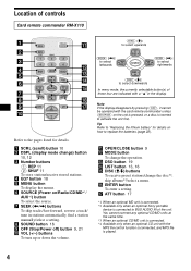
Refer to the pages listed for details. a SCRL (scroll) button 10 b DSPL (display mode change) button 10, 12 c Number buttons (1) REP 11 (2) SHUF 11 To store stations/receive stored stations. SOUND SOURCE DISC - d EQ7 button 18 e MENU button To display the menus. SEEK+ ENTER OFF + ATT VOL - f SOURCE (Power on/Radio/CD/MD*1/ AUX*2) button To select the source. g SEEK ( Location of controls Card remote commander RM-X110 SCRL DSPL REP 1 4 EQ7 OPEN/CLOSE SHUF 2 5 MODE 3 6 DSO MENU DISC + LIST SEEK-
Refer to the pages listed for details. a SCRL (scroll) button 10 b DSPL (display mode change) button 10, 12 c Number buttons (1) REP 11 (2) SHUF 11 To store stations/receive stored stations. SOUND SOURCE DISC - d EQ7 button 18 e MENU button To display the menus. SEEK+ ENTER OFF + ATT VOL - f SOURCE (Power on/Radio/CD/MD*1/ AUX*2) button To select the source. g SEEK ( Location of controls Card remote commander RM-X110 SCRL DSPL REP 1 4 EQ7 OPEN/CLOSE SHUF 2 5 MODE 3 6 DSO MENU DISC + LIST SEEK-
Operating Instructions
Page 5
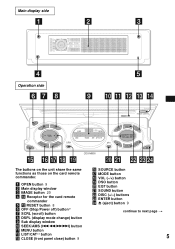
...side Operation side CDX-M800 The buttons on the unit share the same functions as those on the card remote commander. a OPEN button 9 b Main display window c IMAGE button 20 d qf Receptor for the card remote commander e qs RESET button 8 f OFF (Stop/Power off) button...*1 g SCRL (scroll) button h DSPL (display mode change) button i Sub display window j SEEK/AMS (.m/M>) button k MENU button m LIST/CAT*2 button o CLOSE (front panel close) button 9 p SOURCE button q MODE button r VOL (-/+) button s DSO button t EQ7 button u SOUND button v DISC (+/-) buttons w ENTER...
...side Operation side CDX-M800 The buttons on the unit share the same functions as those on the card remote commander. a OPEN button 9 b Main display window c IMAGE button 20 d qf Receptor for the card remote commander e qs RESET button 8 f OFF (Stop/Power off) button...*1 g SCRL (scroll) button h DSPL (display mode change) button i Sub display window j SEEK/AMS (.m/M>) button k MENU button m LIST/CAT*2 button o CLOSE (front panel close) button 9 p SOURCE button q MODE button r VOL (-/+) button s DSO button t EQ7 button u SOUND button v DISC (+/-) buttons w ENTER...
Operating Instructions
Page 6
.... If you have any other soft drinks onto the unit or discs. 6 *1 Warning when installing in a car without an ACC (accessory) position on the unit until the moisture has evaporated. Otherwise, the display does not turn off before operating it. • Power antenna will not operate properly. Moisture condensation On a rainy day... the lenses and display of the unit. Precautions • If your car has been parked in a very damp area, moisture condensation may divert your nearest Sony dealer.
.... If you have any other soft drinks onto the unit or discs. 6 *1 Warning when installing in a car without an ACC (accessory) position on the unit until the moisture has evaporated. Otherwise, the display does not turn off before operating it. • Power antenna will not operate properly. Moisture condensation On a rainy day... the lenses and display of the unit. Precautions • If your car has been parked in a very damp area, moisture condensation may divert your nearest Sony dealer.
Operating Instructions
Page 21
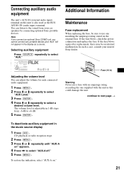
...MD unit, you cannot connect any portable devices and "AUX" will not appear in 1 dB steps from your nearest Sony dealer. In such a case, consult your car speakers by connecting optional Sony portable devices. To restore the indication, select "AUX-A on " appears. 4 Press , to use a fuse ... used as a source. Additional Information Maintenance Fuse replacement When replacing the fuse, be an internal malfunction. If the fuse blows, check the power connection and replace the fuse. Adjusting the volume level You can listen to the sound from -6 dB to select a desired volume level....
...MD unit, you cannot connect any portable devices and "AUX" will not appear in 1 dB steps from your nearest Sony dealer. In such a case, consult your car speakers by connecting optional Sony portable devices. To restore the indication, select "AUX-A on " appears. 4 Press , to use a fuse ... used as a source. Additional Information Maintenance Fuse replacement When replacing the fuse, be an internal malfunction. If the fuse blows, check the power connection and replace the fuse. Adjusting the volume level You can listen to the sound from -6 dB to select a desired volume level....
Operating Instructions
Page 23
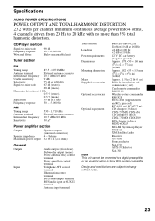
... channel minimum continuous average power into 4 ohms, 4 channels driven from 20 Hz to 20 kHz with an RCA pin cord) RC-61 (1 m), RC-62 (2 m) CD changer (10 discs) CDX-757MX, CDX-656 CD changer (6 discs) CDX-T70MX, CDX-T69 MD changer (6 discs) MDX-66XLP MG-MS System-up Player MGS-X1 XM Satellite ... be connected to a digital preamplifier or an equalizer which is Sony BUS system compatible. CD Player section Signal-to-noise ratio Frequency response Wow and flutter 90 dB 10 - 20,000 Hz Below measurable limit Tuner section FM Tuning range 87.5 - 107.9 MHz Antenna terminal External antenna...
... channel minimum continuous average power into 4 ohms, 4 channels driven from 20 Hz to 20 kHz with an RCA pin cord) RC-61 (1 m), RC-62 (2 m) CD changer (10 discs) CDX-757MX, CDX-656 CD changer (6 discs) CDX-T70MX, CDX-T69 MD changer (6 discs) MDX-66XLP MG-MS System-up Player MGS-X1 XM Satellite ... be connected to a digital preamplifier or an equalizer which is Sony BUS system compatible. CD Player section Signal-to-noise ratio Frequency response Wow and flutter 90 dB 10 - 20,000 Hz Below measurable limit Tuner section FM Tuning range 87.5 - 107.9 MHz Antenna terminal External antenna...
Operating Instructions
Page 24
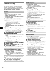
... for a 2-speaker system. Troubleshooting The following checklist will help you remedy problems you may not play due to its recording equipment or the disc condition. The power is hampered by noises. The contents of the car antenna. • The auto antenna will not go up. t Set BlackOut to off... (page 19). 24 The leads are not matched correctly with your car has a built-in FM/ AM antenna in a sturdy part of the car's antenna ...
... for a 2-speaker system. Troubleshooting The following checklist will help you remedy problems you may not play due to its recording equipment or the disc condition. The power is hampered by noises. The contents of the car antenna. • The auto antenna will not go up. t Set BlackOut to off... (page 19). 24 The leads are not matched correctly with your car has a built-in FM/ AM antenna in a sturdy part of the car's antenna ...
Product Guide / Specifications
Page 1
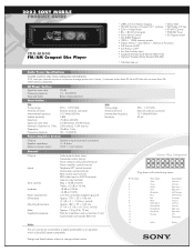
... 16 Plug shown with no more than 5% total harmonic distortion. 2003 SONY MOBILE PRODUCT GUIDE CDX-M800 FM/AM Compact Disc Player • (ABP) w/FL Full Motion Display • DSO, EQ7 • CD/MD Control w/Custom File™ memory • XM Ready, CD Text • 52W x 4 High Power • XT-XM1 Control • 8fs, 1-Bit D/A Converter • SSIR...
... 16 Plug shown with no more than 5% total harmonic distortion. 2003 SONY MOBILE PRODUCT GUIDE CDX-M800 FM/AM Compact Disc Player • (ABP) w/FL Full Motion Display • DSO, EQ7 • CD/MD Control w/Custom File™ memory • XM Ready, CD Text • 52W x 4 High Power • XT-XM1 Control • 8fs, 1-Bit D/A Converter • SSIR...
Service Manual
Page 2
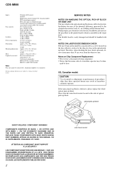
...NE REMPLACER CES COMPOSANTS QUE PAR DES PIÈCES SONY DONT LES NUMÉROS SONT DONNÉS DANS CE MANUEL OU DANS LES ...adjustments or performance of a tantalum capacitor may result in hazardous radiation exposure. CDX-M800 Inputs Tone controls Loudness Power requirements Dimensions Mounting dimensions Mass Supplied accessories Telephone ATT control terminal Illumination control terminal...difference generated by heat. NOTES ON LASER DIODE EMISSION CHECK The laser beam on the disc reflective surface by the objective lens in the optical pickup block. COMPONENTS IDENTIFIED BY ...
...NE REMPLACER CES COMPOSANTS QUE PAR DES PIÈCES SONY DONT LES NUMÉROS SONT DONNÉS DANS CE MANUEL OU DANS LES ...adjustments or performance of a tantalum capacitor may result in hazardous radiation exposure. CDX-M800 Inputs Tone controls Loudness Power requirements Dimensions Mounting dimensions Mass Supplied accessories Telephone ATT control terminal Illumination control terminal...difference generated by heat. NOTES ON LASER DIODE EMISSION CHECK The laser beam on the disc reflective surface by the objective lens in the optical pickup block. COMPONENTS IDENTIFIED BY ...
Service Manual
Page 6
SOUND SOURCE DISC - CDX-M800 SECTION 1 GENERAL This section is extracted from instruction manual. Refer to the pages listed for details. d EQ7 button 18 e MENU button To display the menus. f SOURCE (Power on/Radio/CD/MD*1/ AUX*2) button To select the source. SEEK+ ENTER OFF + AT T VOL - g SEEK ( Location of controls (US, Canadian Model) Card...
SOUND SOURCE DISC - CDX-M800 SECTION 1 GENERAL This section is extracted from instruction manual. Refer to the pages listed for details. d EQ7 button 18 e MENU button To display the menus. f SOURCE (Power on/Radio/CD/MD*1/ AUX*2) button To select the source. SEEK+ ENTER OFF + AT T VOL - g SEEK ( Location of controls (US, Canadian Model) Card...
Service Manual
Page 19
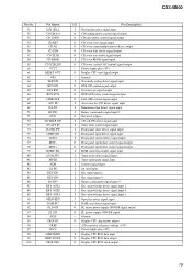
...VREF AVCC DISP SI/RX DISP SO/TX DISP CKO I/O Pin Description I RAM reset detect signal input O FL driver power supply ON/OFF signal output O FL power supply ON/OFF signal - output O CD servo data strobe signal output O CD servo text strobe signal output I -DET... RFOK signal input O CD servo crystal OSC control signal output - Power supply pin (+5V) O Display CPU reset signal output - Power supply pin (+5V) I Display CPU BUS data input O Display CPU BUS data output O Display CPU BUS clock output CDX-M800 19 Ground O Display CPU chip enable output - A/D converter reference ...
...VREF AVCC DISP SI/RX DISP SO/TX DISP CKO I/O Pin Description I RAM reset detect signal input O FL driver power supply ON/OFF signal output O FL power supply ON/OFF signal - output O CD servo data strobe signal output O CD servo text strobe signal output I -DET... RFOK signal input O CD servo crystal OSC control signal output - Power supply pin (+5V) O Display CPU reset signal output - Power supply pin (+5V) I Display CPU BUS data input O Display CPU BUS data output O Display CPU BUS clock output CDX-M800 19 Ground O Display CPU chip enable output - A/D converter reference ...
Service Manual
Page 20
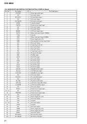
... used . (Open) 10 RESET I FL serial clock input 20 Ground 13 XIN I Flash write-in signal input 45 - 59 NC O Not used. (Open) 60 VCC O Power supply pin (+5V) 61 NC O Not used. (Open) 62 VSS O Ground 63 - 93 NC O Not used . (Open) 96 VREF - Pin Name I/O Pin Description 1 SYS RST... serial data output 4 NC O Not used. (Open) 5 FL CLK IN I FL serial clock input 6 BYTE I L fixed terminal 7 CNVSS I Main clock signal input (30MHz) 14 VCC - CDX-M800 • IC2 M30833FJGP-066 (DISPLAY SYSTEM CONTROL) (DISPLAY Board) Pin No.
... used . (Open) 10 RESET I FL serial clock input 20 Ground 13 XIN I Flash write-in signal input 45 - 59 NC O Not used. (Open) 60 VCC O Power supply pin (+5V) 61 NC O Not used. (Open) 62 VSS O Ground 63 - 93 NC O Not used . (Open) 96 VREF - Pin Name I/O Pin Description 1 SYS RST... serial data output 4 NC O Not used. (Open) 5 FL CLK IN I FL serial clock input 6 BYTE I L fixed terminal 7 CNVSS I Main clock signal input (30MHz) 14 VCC - CDX-M800 • IC2 M30833FJGP-066 (DISPLAY SYSTEM CONTROL) (DISPLAY Board) Pin No.
Service Manual
Page 22
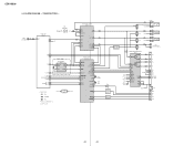
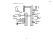
... R -3 L -4 AUDIO OUT REAR R Q103 ILLUMI CHECK Q907 ACC DET Q102 MUTE DRIVE Q401,402 Q470 +10V AU+8V +5V DR+6V A+5V AU+5V D+5V POWER AMP/POWER SUPPLY IC201 5 FL 12 3 RL 11 2 SDA 4 SCL 16 22 STB 25 DIAG 34 DISP;B 30 AU8V 37 U-COM 33 MECHA 31 SERVO 9 7 R-CH...) TUNER UNIT TUX501 1 ANT L4 R3 CD SECTION (Page 21) A CDL AM SDA 14 SCL 13 RDS 9 QUALITY 5 AEP,UK,E MODEL RDS DECODER IC502 16 FM DET 4 OSCD SDA 9 SCL 10 5 OSCI X501 4.3MHz DAVN 8 TU MUTE 7 MUTE CONDITION 8 S-METER 6 SDA 17 EEPROM SCL 16 • Signal path...
... R -3 L -4 AUDIO OUT REAR R Q103 ILLUMI CHECK Q907 ACC DET Q102 MUTE DRIVE Q401,402 Q470 +10V AU+8V +5V DR+6V A+5V AU+5V D+5V POWER AMP/POWER SUPPLY IC201 5 FL 12 3 RL 11 2 SDA 4 SCL 16 22 STB 25 DIAG 34 DISP;B 30 AU8V 37 U-COM 33 MECHA 31 SERVO 9 7 R-CH...) TUNER UNIT TUX501 1 ANT L4 R3 CD SECTION (Page 21) A CDL AM SDA 14 SCL 13 RDS 9 QUALITY 5 AEP,UK,E MODEL RDS DECODER IC502 16 FM DET 4 OSCD SDA 9 SCL 10 5 OSCI X501 4.3MHz DAVN 8 TU MUTE 7 MUTE CONDITION 8 S-METER 6 SDA 17 EEPROM SCL 16 • Signal path...
Service Manual
Page 23
... FL DAT2 3 FL DAT3 FL+ FLFLVDD GCP T800 5 FL CONTROL 4 11 IC301 2 1 DC-DC CONVERTER IC800 23 GCP2 25 GCP1 27 GCP4 28 GCP3 FL POWER CONTROL Q801,802 93 FL ON BATT SYSTEM CONTROL IC303 (3/3) 30 UNI SI 29 UNI SO SIRCS 1 31 UNI CKO 64 BUS ON 65 SYSRST.../CLOSE9 3 14 16 FP CTRL 2 I-DET 76 OPEN SW 75 CLOSE SW 74 I-DET Q305 7 I-DET 3 IC308 SW900 (OPEN/CLOSE) LED CONTROL Q503,504 D512 (DISC IN) OPEN KEY 90 S931 (OPEN) CDX-M800 23 23
... FL DAT2 3 FL DAT3 FL+ FLFLVDD GCP T800 5 FL CONTROL 4 11 IC301 2 1 DC-DC CONVERTER IC800 23 GCP2 25 GCP1 27 GCP4 28 GCP3 FL POWER CONTROL Q801,802 93 FL ON BATT SYSTEM CONTROL IC303 (3/3) 30 UNI SI 29 UNI SO SIRCS 1 31 UNI CKO 64 BUS ON 65 SYSRST.../CLOSE9 3 14 16 FP CTRL 2 I-DET 76 OPEN SW 75 CLOSE SW 74 I-DET Q305 7 I-DET 3 IC308 SW900 (OPEN/CLOSE) LED CONTROL Q503,504 D512 (DISC IN) OPEN KEY 90 S931 (OPEN) CDX-M800 23 23
Service Manual
Page 24
...indicated.) Caution: Pattern face side: Parts on the parts face side seen from the (Side B) pattern face are taken with regulated dc power supply from ACC and BATT cords. • Voltages are in µF unless otherwise noted. Note: The components identified by mark 0 ...é. Parts face side: Parts on the pattern face side seen from the (Side A) parts face are indicated. • Abbreviation CND : Canadian model 24 CDX-M800 4-5. Main Board - (MODE: FM) 1 3.2Vp-p 4.3MHz IC502 4 (OSCD) 2 1.8Vp-p 32.768kHz IC303 9 (XOUT) 3 3.6Vp-p 6MHz IC303 qa (OSCOUT) • Waveform...
...indicated.) Caution: Pattern face side: Parts on the parts face side seen from the (Side B) pattern face are taken with regulated dc power supply from ACC and BATT cords. • Voltages are in µF unless otherwise noted. Note: The components identified by mark 0 ...é. Parts face side: Parts on the pattern face side seen from the (Side A) parts face are indicated. • Abbreviation CND : Canadian model 24 CDX-M800 4-5. Main Board - (MODE: FM) 1 3.2Vp-p 4.3MHz IC502 4 (OSCD) 2 1.8Vp-p 32.768kHz IC303 9 (XOUT) 3 3.6Vp-p 6MHz IC303 qa (OSCOUT) • Waveform...
Service Manual
Page 36
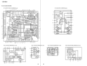
... 26 DVDD IC2 BA5810FP-E2 (SERVO Board) FWD 1 28 BIAS REV 2 LOADING PRE FWD REV LDCONT 3 PS 4 IN1 5 X3 POWER SAVE 7.5k - CH1-4 MUTE 21 MUTE 16k POWVCC34 (CH3,CH4) 20 POWVCC 19 GND 10k LEVEL SHIFT 10k 10k LEVEL SHIFT 10k ...MAD PSWN 20 19 18 17 16 15 14 13 12 11 MULTI PATH DETECTOR 57kHz 8th ORDER BAND-PASS FILTER POWER SUPPLY & RESET PAUSE DETECTOR CLOCKED COMPARATOR SIGNAL QUALITY DECODER 4 CLOCK 54 RDS/RDBS DEMODULATOR RDS/RDBS DECODER INTERFACE ...RAMP VOLTAGE COMPARATOR SOFT START ∑ AMP CURRENT SENSE VOLTAGE ERROR AMP 1 1.25V REF. CDX-M800 4-15.
... 26 DVDD IC2 BA5810FP-E2 (SERVO Board) FWD 1 28 BIAS REV 2 LOADING PRE FWD REV LDCONT 3 PS 4 IN1 5 X3 POWER SAVE 7.5k - CH1-4 MUTE 21 MUTE 16k POWVCC34 (CH3,CH4) 20 POWVCC 19 GND 10k LEVEL SHIFT 10k 10k LEVEL SHIFT 10k ...MAD PSWN 20 19 18 17 16 15 14 13 12 11 MULTI PATH DETECTOR 57kHz 8th ORDER BAND-PASS FILTER POWER SUPPLY & RESET PAUSE DETECTOR CLOCKED COMPARATOR SIGNAL QUALITY DECODER 4 CLOCK 54 RDS/RDBS DEMODULATOR RDS/RDBS DECODER INTERFACE ...RAMP VOLTAGE COMPARATOR SOFT START ∑ AMP CURRENT SENSE VOLTAGE ERROR AMP 1 1.25V REF. CDX-M800 4-15.

Service Manual
Page 38
CDX-M800 IC401 TDA7416 (MAIN Board (1/2)) ACINR ACOUTL ACINL VREFOUT VDD AC2INL AC2OUTL FILOL OUTLF OUTLR NC 33 32 31 30 29 28 27 26 HIGH PASS ... CREF 38 NC 39 AML 40 AMR 41 MDL 42 MDR 43 AUXL 44 IN-GAIN MAIN SOURCE REAR SELECTOR SELECTOR INPUT MULTIPLEXER 12345 67 POWER SUPPLY 8 9 10 11 SOFT STEP FADER SOFT STEP FADER MIXER SOFT STEP FADER SOFT STEP FADER HIGH PASS FILTER2 SOFT STEP FADER ZERO CROSS SPECTRUM...
CDX-M800 IC401 TDA7416 (MAIN Board (1/2)) ACINR ACOUTL ACINL VREFOUT VDD AC2INL AC2OUTL FILOL OUTLF OUTLR NC 33 32 31 30 29 28 27 26 HIGH PASS ... CREF 38 NC 39 AML 40 AMR 41 MDL 42 MDR 43 AUXL 44 IN-GAIN MAIN SOURCE REAR SELECTOR SELECTOR INPUT MULTIPLEXER 12345 67 POWER SUPPLY 8 9 10 11 SOFT STEP FADER SOFT STEP FADER MIXER SOFT STEP FADER SOFT STEP FADER HIGH PASS FILTER2 SOFT STEP FADER ZERO CROSS SPECTRUM...
Service Manual
Page 39
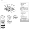
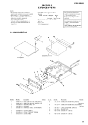
...-790-09 CORD (WITH CONNECTOR) (POWER) (US,CND,E) CORD (WITH CONNECTOR) (ISO) (POWER) (AEP,UK) LABEL (OP CAUTION) (AEP,UK,E) BRACKET (CD) SCREW +PTT 2.6X4 (S) 7-685-792-09 SCREW +PTT 2.6X6 (S) 39 SECTION 5 EXPLODED VIEWS • Color Indication of this parts list. • Abbreviation CND: Canadian model CDX-M800 The components identified by mark...
...-790-09 CORD (WITH CONNECTOR) (POWER) (US,CND,E) CORD (WITH CONNECTOR) (ISO) (POWER) (AEP,UK) LABEL (OP CAUTION) (AEP,UK,E) BRACKET (CD) SCREW +PTT 2.6X4 (S) 7-685-792-09 SCREW +PTT 2.6X6 (S) 39 SECTION 5 EXPLODED VIEWS • Color Indication of this parts list. • Abbreviation CND: Canadian model CDX-M800 The components identified by mark...


