XM Satellite Radio Operating manual
Page 2
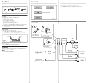
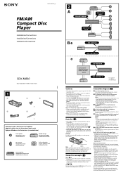
...such as in a car parked in or under the trunk should not be used because of its shape. The fuel tank should be no wire harnesses or pipes under the floor carpet, where the heat dissipation from the heater. •Do not install the unit under the place where... other cords have been connected. • Run all other equipment in direct sunlight). - Connection Connection example XM Antenna* XT-XM1 CD/MD changer* Connection diagram Sony BUS Compatible Car Audio* Cautions • This unit is not subject to direct sunlight. - Black RCA pin cord (not supplied) BUS cable (not supplied) ...
...such as in a car parked in or under the trunk should not be used because of its shape. The fuel tank should be no wire harnesses or pipes under the floor carpet, where the heat dissipation from the heater. •Do not install the unit under the place where... other cords have been connected. • Run all other equipment in direct sunlight). - Connection Connection example XM Antenna* XT-XM1 CD/MD changer* Connection diagram Sony BUS Compatible Car Audio* Cautions • This unit is not subject to direct sunlight. - Black RCA pin cord (not supplied) BUS cable (not supplied) ...
Installation/Connection Instructions
Page 1
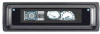
...control lead (blue) supplies +12 V DC when you connect an optional power amplifier and do not use the built-in speaker wires installed in your car if the unit shares a common negative (-) lead for the right and left speaker. • Do not... active speakers (with this product will be higher than the sum of each other system may spring out. 3-251-125-11 (1) FM/AM Compact Disc Player Installation/Connections Installation/Connexions Instalación/Conexiones CDX-M800 Sony Corporation © 2003 Printed in Korea 1 1 2 3 × 4 4 5 × 2 Equipment used with those in ...
...control lead (blue) supplies +12 V DC when you connect an optional power amplifier and do not use the built-in speaker wires installed in your car if the unit shares a common negative (-) lead for the right and left speaker. • Do not... active speakers (with this product will be higher than the sum of each other system may spring out. 3-251-125-11 (1) FM/AM Compact Disc Player Installation/Connections Installation/Connexions Instalación/Conexiones CDX-M800 Sony Corporation © 2003 Printed in Korea 1 1 2 3 × 4 4 5 × 2 Equipment used with those in ...
Product Guide / Specifications
Page 1
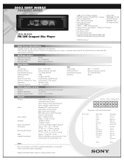
Design and Specifications subject to a digital preamplifier or an equalizer which is Sony BUS system compatible. Pin Number 1 2 3 4 5 6 7 8 9 10 11 12 13 14 15 16 Wire Color White Green Purple Gray Blue/white Blue Red Black White/black Green/black Purple/black Gray/... 90 dB 10 – 20,000 Hz Below measurable limit Tuner Section FM Tuning range Antenna terminal Intermediate frequency Usable sensitivity Selectivity Signal-to 20 kHz with wires facing viewer. 2003 SONY MOBILE PRODUCT GUIDE CDX-M800 FM/AM Compact Disc Player • (ABP) w/FL Full Motion Display • DSO, EQ7 ...
Design and Specifications subject to a digital preamplifier or an equalizer which is Sony BUS system compatible. Pin Number 1 2 3 4 5 6 7 8 9 10 11 12 13 14 15 16 Wire Color White Green Purple Gray Blue/white Blue Red Black White/black Green/black Purple/black Gray/... 90 dB 10 – 20,000 Hz Below measurable limit Tuner Section FM Tuning range Antenna terminal Intermediate frequency Usable sensitivity Selectivity Signal-to 20 kHz with wires facing viewer. 2003 SONY MOBILE PRODUCT GUIDE CDX-M800 FM/AM Compact Disc Player • (ABP) w/FL Full Motion Display • DSO, EQ7 ...
Service Manual
Page 5
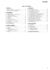
...GENERAL Location of Controls 6 Connection example (US, Canadian Model 6 Connections (US, Canadian Model 7 2. Cam (L 15 3-3. DIAGRAMS 4-1. Printed Wiring Board -Sub Section 32 4-12. EXPLODED VIEWS 5-1. Main Board Section 41 5-4. CD Mechanism Section (2 44 5-7. CD Mechanism Block, Front Panel... Block Diagram -Display Section 23 4-5. Schematic Diagram -CD Mechanism Section 25 4-7. Cam Section 40 5-3. ELECTRICAL PARTS LIST 46 5 CDX-M800 TABLE OF CONTENTS 1. DISASSEMBLY 2-1. Sub Panel (CD) Sub Assy 9 2-4. Motor Block Assy, Cam (R) Assy 10 2-5. Chassis ...
...GENERAL Location of Controls 6 Connection example (US, Canadian Model 6 Connections (US, Canadian Model 7 2. Cam (L 15 3-3. DIAGRAMS 4-1. Printed Wiring Board -Sub Section 32 4-12. EXPLODED VIEWS 5-1. Main Board Section 41 5-4. CD Mechanism Section (2 44 5-7. CD Mechanism Block, Front Panel... Block Diagram -Display Section 23 4-5. Schematic Diagram -CD Mechanism Section 25 4-7. Cam Section 40 5-3. ELECTRICAL PARTS LIST 46 5 CDX-M800 TABLE OF CONTENTS 1. DISASSEMBLY 2-1. Sub Panel (CD) Sub Assy 9 2-4. Motor Block Assy, Cam (R) Assy 10 2-5. Chassis ...
Service Manual
Page 11
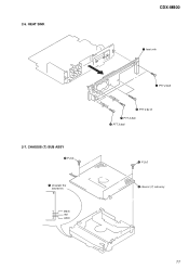
black red white CDX-M800 5 heat sink 4 PTT 2.6x6 3 PTT 2.6x12 1 PTT 2.6x6 2 PTT 2.6x6 3 P 2x3 4 chassis (T) sub assy 11 CHASSIS (T) SUB ASSY 2 P 2x3 1 Unsolder the lead wires. HEAT SINK 2-7. 2-6.
black red white CDX-M800 5 heat sink 4 PTT 2.6x6 3 PTT 2.6x12 1 PTT 2.6x6 2 PTT 2.6x6 3 P 2x3 4 chassis (T) sub assy 11 CHASSIS (T) SUB ASSY 2 P 2x3 1 Unsolder the lead wires. HEAT SINK 2-7. 2-6.
Service Manual
Page 12
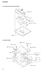
LEVER SECTION, IN SELF SW BOARD 5 guide (disc) 6 lever (R) 3 tension spring (LR) 7 lever (L) 1 special screw 2 IN SELF SW board 4 claws 2-9. black yellow optical pick-up block 12 CDX-M800 2-8. SERVO BOARD 6 special screws 2 Removal the solders. 8 SERVO board 7 special screw 9 FLEXIBLE board 1 CN3 4 P 2x3 5 loading motor assy 3 Unsolder the lead wires.
LEVER SECTION, IN SELF SW BOARD 5 guide (disc) 6 lever (R) 3 tension spring (LR) 7 lever (L) 1 special screw 2 IN SELF SW board 4 claws 2-9. black yellow optical pick-up block 12 CDX-M800 2-8. SERVO BOARD 6 special screws 2 Removal the solders. 8 SERVO board 7 special screw 9 FLEXIBLE board 1 CN3 4 P 2x3 5 loading motor assy 3 Unsolder the lead wires.
Service Manual
Page 24
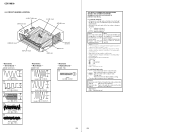
... 32.768kHz IC303 9 (XOUT) 3 3.6Vp-p 6MHz IC303 qa (OSCOUT) • Waveform - Display Board - (MODE: FM) 1 1.5Vp-p 30MHz IC2 qa (XOUT) 24 THIS NOTE IS COMMON FOR PRINTED WIRING BOARDS AND SCHEMATIC DIAGRAMS. (In addition to this, the necessary note is dc 14.4V and fed with regulated dc... are in Ω and 1/4 W or less unless otherwise specified. • % : indicates tolerance. • f : internal component. • C : panel designation. CDX-M800 4-5. Replace only with a VOM (Input impedance 10 MΩ). Ne les remplacer que par une piéce portant le numéro spécifi...
... 32.768kHz IC303 9 (XOUT) 3 3.6Vp-p 6MHz IC303 qa (OSCOUT) • Waveform - Display Board - (MODE: FM) 1 1.5Vp-p 30MHz IC2 qa (XOUT) 24 THIS NOTE IS COMMON FOR PRINTED WIRING BOARDS AND SCHEMATIC DIAGRAMS. (In addition to this, the necessary note is dc 14.4V and fed with regulated dc... are in Ω and 1/4 W or less unless otherwise specified. • % : indicates tolerance. • f : internal component. • C : panel designation. CDX-M800 4-5. Replace only with a VOM (Input impedance 10 MΩ). Ne les remplacer que par une piéce portant le numéro spécifi...
Service Manual
Page 26
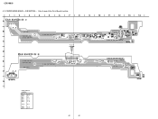
CD MECHANISM SECTION - • Refer to page 24 for Circuit Boards Location. 14 13 12 11 10 9 8 7 6 5 4 3 2 1 A CN2 B C D E F G H I J 26 26 CDX-M800 4-7. PRINTED WIRING BOARDS -
CD MECHANISM SECTION - • Refer to page 24 for Circuit Boards Location. 14 13 12 11 10 9 8 7 6 5 4 3 2 1 A CN2 B C D E F G H I J 26 26 CDX-M800 4-7. PRINTED WIRING BOARDS -
Service Manual
Page 28
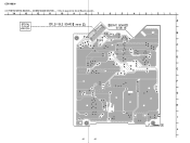
No. MAIN SECTION - • Refer to page 24 for Circuit Boards Location. 14 13 12 11 10 9 8 7 6 • Semiconductor Location Ref. CDX-M800 4-8. Location Ref. No. (D101) (D102) (D103) (D104) (D105) (D106) (D109) (D110) (D111) (D112) (D113) (D114) (D115) (D116) (D117) (D118) (D119) (D120) (D121) (D122) D302 D303 ... C416 C417 C810 C809 IC800 R422 C431 R478 E C526 C525 C528 C527 R518 C521 F IC502 C520 R519 G T800 H D826 L800 C802 I CNP909 J (Page 34) PRINTED WIRING BOARDS -
No. MAIN SECTION - • Refer to page 24 for Circuit Boards Location. 14 13 12 11 10 9 8 7 6 • Semiconductor Location Ref. CDX-M800 4-8. Location Ref. No. (D101) (D102) (D103) (D104) (D105) (D106) (D109) (D110) (D111) (D112) (D113) (D114) (D115) (D116) (D117) (D118) (D119) (D120) (D121) (D122) D302 D303 ... C416 C417 C810 C809 IC800 R422 C431 R478 E C526 C525 C528 C527 R518 C521 F IC502 C520 R519 G T800 H D826 L800 C802 I CNP909 J (Page 34) PRINTED WIRING BOARDS -
Service Manual
Page 32
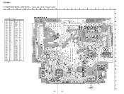
Location D506 D507 D511 D512 D513 D514 B-10 B-6 C-8 C-8 E-13 C-10 IC503 B-13 Q503 Q504 C-9 B-10 32 32 D507 D511 R534 R532 D506 C533 9 10 11 12 13 14 Q504 R536 C539 Q503 R533 R531 D514 C540 FB503 C535 C536 C537 SW501 IC503 R538 C538 R509 D513 C535 PRINTED WIRING BOARD - No. CDX-M800 4-11. SUB SECTION - • Refer to page 24 for Circuit Boards Location. 1 2 3 4 5 6 7 8 A B D512 C (Page 29) D CN501 E F CN502 G • Semiconductor Location Ref.
Location D506 D507 D511 D512 D513 D514 B-10 B-6 C-8 C-8 E-13 C-10 IC503 B-13 Q503 Q504 C-9 B-10 32 32 D507 D511 R534 R532 D506 C533 9 10 11 12 13 14 Q504 R536 C539 Q503 R533 R531 D514 C540 FB503 C535 C536 C537 SW501 IC503 R538 C538 R509 D513 C535 PRINTED WIRING BOARD - No. CDX-M800 4-11. SUB SECTION - • Refer to page 24 for Circuit Boards Location. 1 2 3 4 5 6 7 8 A B D512 C (Page 29) D CN501 E F CN502 G • Semiconductor Location Ref.
Service Manual
Page 34
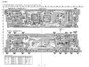
... D70 D901 D902 D908 IC1 IC2 IC62 IC301 F-2 B-1 B-4 B-10 C-8 B-6 C-2 C-7 LED901 LED902 LED903 LED905 LED906 LED908 LED909 LED911 LED912 LED913 Location F-2 H-2 H-1 F-3 F-4 H-4 A-13 H-14 H-12 H-12 Ref. CDX-M800 4-13. No. DISPLAY SECTION - • Refer to page 24 for Circuit Boards Location. 1 2 3 4 5 6 7 A C905 R988 LED931 B S931 D901 C914 C904 IC62 C903 R969 C R968 C902... S918 LED920 S921 LED921 S920 R914 R925 R955 R960 LED912 S912 LED913 R921 R953 R958 R923 S911 R922 S913 LED911 • Semiconductor Location Ref. PRINTED WIRING BOARD - No.
... D70 D901 D902 D908 IC1 IC2 IC62 IC301 F-2 B-1 B-4 B-10 C-8 B-6 C-2 C-7 LED901 LED902 LED903 LED905 LED906 LED908 LED909 LED911 LED912 LED913 Location F-2 H-2 H-1 F-3 F-4 H-4 A-13 H-14 H-12 H-12 Ref. CDX-M800 4-13. No. DISPLAY SECTION - • Refer to page 24 for Circuit Boards Location. 1 2 3 4 5 6 7 A C905 R988 LED931 B S931 D901 C914 C904 IC62 C903 R969 C R968 C902... S918 LED920 S921 LED921 S920 R914 R925 R955 R960 LED912 S912 LED913 R921 R953 R958 R923 S911 R922 S913 LED911 • Semiconductor Location Ref. PRINTED WIRING BOARD - No.


