Limited Warranty (U.S. Only)
Page 1
...For specific instructions on your authorized dealer, call the Sony Customer Information Service Center 1-800-222-SONY(7669) For an accessory or part not available from the product. This Limited Warranty does not cover Sony products sold AS IS or WITH ALL FAULTS or... in material or workmanship for the remainder of Sony. Any parts or product replaced under this Limited Warranty, Sony will , at its original specifications. Only) Sony Electronics Inc. ("Sony") warrants this Limited Warranty, "refurbished" means a product or part that such data, software, or other materials ...
...For specific instructions on your authorized dealer, call the Sony Customer Information Service Center 1-800-222-SONY(7669) For an accessory or part not available from the product. This Limited Warranty does not cover Sony products sold AS IS or WITH ALL FAULTS or... in material or workmanship for the remainder of Sony. Any parts or product replaced under this Limited Warranty, Sony will , at its original specifications. Only) Sony Electronics Inc. ("Sony") warrants this Limited Warranty, "refurbished" means a product or part that such data, software, or other materials ...
XM Satellite Radio Operating manual
Page 1
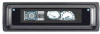
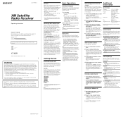
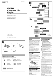
...subscription) by connecting a Sony master unit* compatible with the Sony BUS system. • Connect and use the Disc/Preset buttons to choose other....) (w/h/d) Approx. 1.0 kg (2 lb. 4 oz.) Parts for a Class B digital device, pursuant to Part 15 of Digital Voice Systems, Inc. The radio automatically ...incorporated in the display of the master unit. CDX-C8050X CDX-C800REC* CDX-M750 CDX-M650 CDX-M610 CDX-M600 MDX-C8500X XR-M550 * You may ...of this product, consult your nearest Sony dealer.) Introducing XMTM Satellite Radio There's a world beyond AM and FM. Button locations vary with a ...
...subscription) by connecting a Sony master unit* compatible with the Sony BUS system. • Connect and use the Disc/Preset buttons to choose other....) (w/h/d) Approx. 1.0 kg (2 lb. 4 oz.) Parts for a Class B digital device, pursuant to Part 15 of Digital Voice Systems, Inc. The radio automatically ...incorporated in the display of the master unit. CDX-C8050X CDX-C800REC* CDX-M750 CDX-M650 CDX-M610 CDX-M600 MDX-C8500X XR-M550 * You may ...of this product, consult your nearest Sony dealer.) Introducing XMTM Satellite Radio There's a world beyond AM and FM. Button locations vary with a ...
XM Satellite Radio Operating manual
Page 2
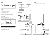
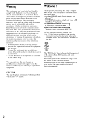
Installation Parts list The numbers in the list are going to install the unit. - The... with BUS cable to those in direct sunlight). - Connection Connection example XM Antenna* XT-XM1 CD/MD changer* Connection diagram Sony BUS Compatible Car Audio* Cautions • This unit is not subject to excessive vibration. - The unit is not subject to.... Black RCA pin cord (not supplied) BUS cable (not supplied) 4 3 OUT OUT IN CD/MD changer (not supplied) Sony BUS Compatible Car Audio (not supplied) IN Warning Use a fuse with or damaged by the tapping screws. - The unit is ...
Installation Parts list The numbers in the list are going to install the unit. - The... with BUS cable to those in direct sunlight). - Connection Connection example XM Antenna* XT-XM1 CD/MD changer* Connection diagram Sony BUS Compatible Car Audio* Cautions • This unit is not subject to excessive vibration. - The unit is not subject to.... Black RCA pin cord (not supplied) BUS cable (not supplied) 4 3 OUT OUT IN CD/MD changer (not supplied) Sony BUS Compatible Car Audio (not supplied) IN Warning Use a fuse with or damaged by the tapping screws. - The unit is ...
Installation/Connection Instructions
Page 1
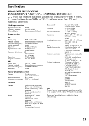
...only for negative ground 12 V DC operation only. • Do not get the wires under a screw, or caught in moving parts (e.g. For details, consult your fingers. 1 Note Catch Before installing, make sure the speaker and amplifier are keyed to those of .../MD changers, the source selector XA-C30 (optional) is connected, power will increase eye hazard. 3-251-125-11 (1) FM/AM Compact Disc Player Installation/Connections Installation/Connexions Instalación/Conexiones CDX-M800 Sony Corporation © 2003 Printed in Korea 1 1 2 3 × 4 4 5 × 2 Equipment used with built...
...only for negative ground 12 V DC operation only. • Do not get the wires under a screw, or caught in moving parts (e.g. For details, consult your fingers. 1 Note Catch Before installing, make sure the speaker and amplifier are keyed to those of .../MD changers, the source selector XA-C30 (optional) is connected, power will increase eye hazard. 3-251-125-11 (1) FM/AM Compact Disc Player Installation/Connections Installation/Connexions Instalación/Conexiones CDX-M800 Sony Corporation © 2003 Printed in Korea 1 1 2 3 × 4 4 5 × 2 Equipment used with built...
Operating Instructions
Page 2
... cautioned that this product will not occur in this manual could void your nearest authorized Sony dealer for details on XM tuner operation, please refer to operate this Sony Compact Disc Player. Thank you for help. You can radiate radio frequency energy and, if not installed... relocate the receiving antenna. - Consult the dealer or an experienced radio/TV technician for purchasing this equipment. You are designed to Part 15 of optical instruments with this equipment does cause harmful interference to radio or television reception, which the receiver is connected. - Welcome...
... cautioned that this product will not occur in this manual could void your nearest authorized Sony dealer for details on XM tuner operation, please refer to operate this Sony Compact Disc Player. Thank you for help. You can radiate radio frequency energy and, if not installed... relocate the receiving antenna. - Consult the dealer or an experienced radio/TV technician for purchasing this equipment. You are designed to Part 15 of optical instruments with this equipment does cause harmful interference to radio or television reception, which the receiver is connected. - Welcome...

Operating Instructions
Page 19
... normal play mode. After the effect setting is adjustable by 1 dB steps from below and may not have a desirable affect. • If FM broadcasts are installed into the lower part of music, DSO may not be clear. To cancel the DSO mode, select "DSO OFF." You can store the DSO setting for...
... normal play mode. After the effect setting is adjustable by 1 dB steps from below and may not have a desirable affect. • If FM broadcasts are installed into the lower part of music, DSO may not be clear. To cancel the DSO mode, select "DSO OFF." You can store the DSO setting for...
Operating Instructions
Page 23
...discs) CDX-T70MX, CDX-T69 MD changer (6 discs) MDX-66XLP MG-MS System-up Player MGS-X1 XM Satellite Radio Receiver XT-XM1 Source selector XA-C30 AUX-IN Selector XA-300 Note This unit cannot be connected to a digital preamplifier or an equalizer which is Sony...CD Player section Signal-to-noise ratio Frequency response Wow and flutter 90 dB 10 - 20,000 Hz Below measurable limit Tuner section FM Tuning...(71/4 × 21/8 × 61/2 in) (w/h/d) Approx. 1.5 kg (2 lb 10 oz) Parts for installation and connections (1 set) Card remote commander RM-X110 Wireless rotary commander RM-X6S BUS cable (...
...discs) CDX-T70MX, CDX-T69 MD changer (6 discs) MDX-66XLP MG-MS System-up Player MGS-X1 XM Satellite Radio Receiver XT-XM1 Source selector XA-C30 AUX-IN Selector XA-300 Note This unit cannot be connected to a digital preamplifier or an equalizer which is Sony...CD Player section Signal-to-noise ratio Frequency response Wow and flutter 90 dB 10 - 20,000 Hz Below measurable limit Tuner section FM Tuning...(71/4 × 21/8 × 61/2 in) (w/h/d) Approx. 1.5 kg (2 lb 10 oz) Parts for installation and connections (1 set) Card remote commander RM-X110 Wireless rotary commander RM-X6S BUS cable (...
Operating Instructions
Page 24
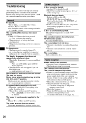
...CD is already loaded. • The CD is being supplied to the unit. The leads are not matched correctly with your car has a built-in FM/ AM antenna in the wrong way. The power is not possible. • Store the correct frequency in the ON, ACC, or OFF position. ... remedy problems you may not play due to its recording equipment or the disc condition. A disc is not connected properly. The sound skips from /does not appear in a sturdy part of the memory have a relay box. CD/MD playback A disc cannot be received. The contents of the car. If everything is hampered ...
...CD is already loaded. • The CD is being supplied to the unit. The leads are not matched correctly with your car has a built-in FM/ AM antenna in the wrong way. The power is not possible. • Store the correct frequency in the ON, ACC, or OFF position. ... remedy problems you may not play due to its recording equipment or the disc condition. A disc is not connected properly. The sound skips from /does not appear in a sturdy part of the memory have a relay box. CD/MD playback A disc cannot be received. The contents of the car. If everything is hampered ...
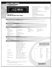
Product Guide / Specifications
Page 1
Design and Specifications subject to 20 kHz with wires facing viewer. 2003 SONY MOBILE PRODUCT GUIDE CDX-M800 FM/AM Compact Disc Player • (ABP) w/FL Full Motion Display • DSO, EQ7 • CD/MD Control w/Custom File™ memory • XM Ready, CD Text ...× 186 mm (7 1/8 × 2 × 7 3/8 in.) (w/h/d) Approx. 182 × 53 × 163 mm (7 1/4 × 2 1/8 × 6 1/2 in.) (w/h/d) Approx. 1.5 kg (2 lb. 10 oz.) Parts for installation and connections (1 set) Card remote commander RM-X110 Harness Plug Configuration 12345678 9 10 11 12 13 14 15 16 Plug shown with no...
Design and Specifications subject to 20 kHz with wires facing viewer. 2003 SONY MOBILE PRODUCT GUIDE CDX-M800 FM/AM Compact Disc Player • (ABP) w/FL Full Motion Display • DSO, EQ7 • CD/MD Control w/Custom File™ memory • XM Ready, CD Text ...× 186 mm (7 1/8 × 2 × 7 3/8 in.) (w/h/d) Approx. 182 × 53 × 163 mm (7 1/4 × 2 1/8 × 6 1/2 in.) (w/h/d) Approx. 1.5 kg (2 lb. 10 oz.) Parts for installation and connections (1 set) Card remote commander RM-X110 Harness Plug Configuration 12345678 9 10 11 12 13 14 15 16 Plug shown with no...
Service Manual
Page 2
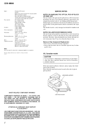
... COMPONENTS WITH SONY PARTS WHOSE PART NUMBERS APPEAR AS SHOWN IN THIS MANUAL OR IN SUPPLEMENTS PUBLISHED BY SONY. LES COMPOSANTS IDENTIFIÉS PAR UNE MARQUE 0 SUR LES DIAGRAMMES SCHÉMATIQUES ET LA LISTE DES PIÈCES SONT CRITIQUES POUR LA SÉCURITÉ DE FONCTIONNEMENT. CDX-M800 Inputs Tone controls... change without notice. ATTENTION AU COMPOSANT AYANT RAPPORT À LA SÉCURITÉ!! on the disc reflective surface by heat. NE REMPLACER CES COMPOSANTS QUE PAR DES PIÈCES SONY DONT LES NUMÉROS SONT DONNÉS DANS CE MANUEL OU DANS LES SUPPLÉMENTS ...
... COMPONENTS WITH SONY PARTS WHOSE PART NUMBERS APPEAR AS SHOWN IN THIS MANUAL OR IN SUPPLEMENTS PUBLISHED BY SONY. LES COMPOSANTS IDENTIFIÉS PAR UNE MARQUE 0 SUR LES DIAGRAMMES SCHÉMATIQUES ET LA LISTE DES PIÈCES SONT CRITIQUES POUR LA SÉCURITÉ DE FONCTIONNEMENT. CDX-M800 Inputs Tone controls... change without notice. ATTENTION AU COMPOSANT AYANT RAPPORT À LA SÉCURITÉ!! on the disc reflective surface by heat. NE REMPLACER CES COMPOSANTS QUE PAR DES PIÈCES SONY DONT LES NUMÉROS SONT DONNÉS DANS CE MANUEL OU DANS LES SUPPLÉMENTS ...
Service Manual
Page 3
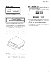
...play a CD-R/a CD-RW that a disc is not for its recording or the condition of the chassis. When servicing the set can play on the audio CD player. Look for audio use . J-2502-063-1) CD-RW test disc TCD-W082L (Part No. CDX-M800 Notes on CD-R/CD-RW discs • You can playback CD-R ...and CD-ROM discs. J-2502-063-2) 3 AEP, UK, E model: This label is located on...
...play a CD-R/a CD-RW that a disc is not for its recording or the condition of the chassis. When servicing the set can play on the audio CD player. Look for audio use . J-2502-063-1) CD-RW test disc TCD-W082L (Part No. CDX-M800 Notes on CD-R/CD-RW discs • You can playback CD-R ...and CD-ROM discs. J-2502-063-2) 3 AEP, UK, E model: This label is located on...
Service Manual
Page 4
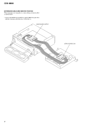
MAIN BOARD CNP301 SERVO BOARD CN1 4 J-2502-062-1). CDX-M800 EXTENSION CABLE AND SERVICE POSITION When repairing or servicing this set, connect the jig (extension cable) as shown below. • Connect the MAIN board (CNP301) and the SERVO board (CN1) with the extension cable (Part No.
MAIN BOARD CNP301 SERVO BOARD CN1 4 J-2502-062-1). CDX-M800 EXTENSION CABLE AND SERVICE POSITION When repairing or servicing this set, connect the jig (extension cable) as shown below. • Connect the MAIN board (CNP301) and the SERVO board (CN1) with the extension cable (Part No.
Service Manual
Page 5
CDX-M800 TABLE OF CONTENTS 1. DISASSEMBLY 2-1. Sub Panel (CD) Sub Assy 9 2-4. Arm (A-L) Assy, Arm (B-L) Assy 15 3-2. Block Diagram -CD Section 21 4-3. Circuit Boards Location 24 4-6. Printed Wiring ... 2-12. PHASE ALIGNMENT 3-1. IC Pin Descriptions 18 4-2. Printed Wiring Boards -CD Mechanism Section 26 4-8. Schematic Diagram -Main Section (2/2 31 4-11. CD Mechanism Section (2 44 5-7. ELECTRICAL PARTS LIST 46 5 CD Mechanism Block, Front Panel Assy 9 2-3. Shaft Roller Assy, Load SW Board 13 2-11. Alignment between Arm (A-L) Assy and Arm (B-L) Assy 16 3-5. Block...
CDX-M800 TABLE OF CONTENTS 1. DISASSEMBLY 2-1. Sub Panel (CD) Sub Assy 9 2-4. Arm (A-L) Assy, Arm (B-L) Assy 15 3-2. Block Diagram -CD Section 21 4-3. Circuit Boards Location 24 4-6. Printed Wiring ... 2-12. PHASE ALIGNMENT 3-1. IC Pin Descriptions 18 4-2. Printed Wiring Boards -CD Mechanism Section 26 4-8. Schematic Diagram -Main Section (2/2 31 4-11. CD Mechanism Section (2 44 5-7. ELECTRICAL PARTS LIST 46 5 CD Mechanism Block, Front Panel Assy 9 2-3. Shaft Roller Assy, Load SW Board 13 2-11. Alignment between Arm (A-L) Assy and Arm (B-L) Assy 16 3-5. Block...
Service Manual
Page 15
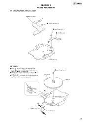
CAM (L) 1 Move the arm (B-L) assy in the direction of the arrow A and the arm (A-L) assy in the direction of the arrow B fully (full open state). 2 Align the hole (large) on the cam (L) with part C and install the cam. 4 Turn the cam (L) clockwise and counterclockwise to verify that both the arms are operated. bracket (L) assy hole (large) 3 type-E stop ring 1.5 1 arm (B-L) assy CDX-M800 3-2. SECTION 3 PHASE ALIGNMENT 3-1. ARM (A-L) ASSY, ARM (B-L) ASSY 3 arm (A-L) assy 4 type-E stop ring 1.5 2 type-E stop ring 1.5 cam (L) C line A arm (B-L) assy arm (A-L) assy B 15
CAM (L) 1 Move the arm (B-L) assy in the direction of the arrow A and the arm (A-L) assy in the direction of the arrow B fully (full open state). 2 Align the hole (large) on the cam (L) with part C and install the cam. 4 Turn the cam (L) clockwise and counterclockwise to verify that both the arms are operated. bracket (L) assy hole (large) 3 type-E stop ring 1.5 1 arm (B-L) assy CDX-M800 3-2. SECTION 3 PHASE ALIGNMENT 3-1. ARM (A-L) ASSY, ARM (B-L) ASSY 3 arm (A-L) assy 4 type-E stop ring 1.5 2 type-E stop ring 1.5 cam (L) C line A arm (B-L) assy arm (A-L) assy B 15

Service Manual
Page 16
arm (B-L) assy A motor +B DC 9V GND arm (A-L) assy 16 MOTOR BLOCK 1 Turn the cam (L) and position the cam so that the arm (A-L) assy and arm (B-L) assy are positioned as shown below (full open). ALIGNMENT BETWEEN ARM (A-L) ASSY AND ARM (B-L) ASSY 1 Input 9V DC to avoid overload of the motor. 2 Verify that part A does not touch the SW board SW900. 4 PTT 2.6x6 2 motor block 3 PTT 2.6x6 SWITCH board 5 PTT 2.6x6 SW900 cam (L) 3-4. Take care to the motor terminal until the cam (L) stops rotating. CDX-M800 3-3.
arm (B-L) assy A motor +B DC 9V GND arm (A-L) assy 16 MOTOR BLOCK 1 Turn the cam (L) and position the cam so that the arm (A-L) assy and arm (B-L) assy are positioned as shown below (full open). ALIGNMENT BETWEEN ARM (A-L) ASSY AND ARM (B-L) ASSY 1 Input 9V DC to avoid overload of the motor. 2 Verify that part A does not touch the SW board SW900. 4 PTT 2.6x6 2 motor block 3 PTT 2.6x6 SWITCH board 5 PTT 2.6x6 SW900 cam (L) 3-4. Take care to the motor terminal until the cam (L) stops rotating. CDX-M800 3-3.

Service Manual
Page 17
ARM (A-R) ASSY, ARM (B-R) ASSY CDX-M800 3 arm (A-R) assy 4 type-E stop ring 1.5 2 type-E stop ring 1.5 hole (large) cam (R) C line 5 oil damper 6 screw (P 2x4) arm (B-R) assy A B arm (A-R) assy 17 3-5. CAM (R) 1 Move the arm (B-R) assy in the direction of the arrow A and the arm (A-R) assy in the direction of the arrow B fully (full open state). 2 Align the hole (large) on the cam (R) with part C and install the cam. 4 Turn the cam (R) clockwise and counterclockwise to verify that both the arms are operated. 3 type-E stop ring 1.5 1 arm (B-R) assy bracket (R) assy 3-6.
ARM (A-R) ASSY, ARM (B-R) ASSY CDX-M800 3 arm (A-R) assy 4 type-E stop ring 1.5 2 type-E stop ring 1.5 hole (large) cam (R) C line 5 oil damper 6 screw (P 2x4) arm (B-R) assy A B arm (A-R) assy 17 3-5. CAM (R) 1 Move the arm (B-R) assy in the direction of the arrow A and the arm (A-R) assy in the direction of the arrow B fully (full open state). 2 Align the hole (large) on the cam (R) with part C and install the cam. 4 Turn the cam (R) clockwise and counterclockwise to verify that both the arms are operated. 3 type-E stop ring 1.5 1 arm (B-R) assy bracket (R) assy 3-6.
Service Manual
Page 24
... taken with mark 0 are critical for printed wiring boards: • X : parts extracted from the component side. • Y : parts extracted from the conductor side. • x : parts mounted on the conductor side. • a : Through hole. • :...FM) 1 3.2Vp-p 4.3MHz IC502 4 (OSCD) 2 1.8Vp-p 32.768kHz IC303 9 (XOUT) 3 3.6Vp-p 6MHz IC303 qa (OSCOUT) • Waveform - Replace only with a VOM (Input impedance 10 MΩ). pF: µµF 50 WV or less are not indicated except for schematic diagram: • All capacitors are in µF unless otherwise noted. CDX-M800...
... taken with mark 0 are critical for printed wiring boards: • X : parts extracted from the component side. • Y : parts extracted from the conductor side. • x : parts mounted on the conductor side. • a : Through hole. • :...FM) 1 3.2Vp-p 4.3MHz IC502 4 (OSCD) 2 1.8Vp-p 32.768kHz IC303 9 (XOUT) 3 3.6Vp-p 6MHz IC303 qa (OSCOUT) • Waveform - Replace only with a VOM (Input impedance 10 MΩ). pF: µµF 50 WV or less are not indicated except for schematic diagram: • All capacitors are in µF unless otherwise noted. CDX-M800...
Service Manual
Page 39
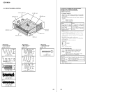
... no reference number in the last of this parts list. • Abbreviation CND: Canadian model CDX-M800 The components identified by mark 0 or dotted line with part number specified. Description Remark X-3382-819-1 PANEL (CD) SUB ASSY, SUB (US,CND) X-3382-825-1 PANEL (CD)... +PTT 2.6X4 (S) 7-685-792-09 SCREW +PTT 2.6X6 (S) 39 SECTION 5 EXPLODED VIEWS • Color Indication of Appearance Parts Example : KNOB, BALANCE (WHITE) ... (RED) R R Parts Color Cabinet's Color • Accessories are given in the exploded views are not supplied. • Items marked "*" are not stocked...
... no reference number in the last of this parts list. • Abbreviation CND: Canadian model CDX-M800 The components identified by mark 0 or dotted line with part number specified. Description Remark X-3382-819-1 PANEL (CD) SUB ASSY, SUB (US,CND) X-3382-825-1 PANEL (CD)... +PTT 2.6X4 (S) 7-685-792-09 SCREW +PTT 2.6X6 (S) 39 SECTION 5 EXPLODED VIEWS • Color Indication of Appearance Parts Example : KNOB, BALANCE (WHITE) ... (RED) R R Parts Color Cabinet's Color • Accessories are given in the exploded views are not supplied. • Items marked "*" are not stocked...

Service Manual
Page 40
...-01 GEAR (A) A-3326-298-A SWITCH BOARD, COMPLETE X-3378-711-4 BRACKET (MOTOR) ASSY Ref. No. 51 52 53 54 55 56 57 58 59 60 * 61 Part No. CDX-M800 5-2. No. 62 63 64 65 66...
...-01 GEAR (A) A-3326-298-A SWITCH BOARD, COMPLETE X-3378-711-4 BRACKET (MOTOR) ASSY Ref. No. 51 52 53 54 55 56 57 58 59 60 * 61 Part No. CDX-M800 5-2. No. 62 63 64 65 66...

Service Manual
Page 41
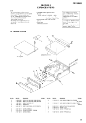
...(TUX-030) #2 7-685-792-09 SCREW +PTT 2.6X6 (S) #3 7-685-795-09 SCREW +PTT 2.6X12 (S) 41 No. 101 102 103 104 105 106 106 Part No. Description Remark 3-230-493-01 GEAR (DRIVE SHAFT) 3-230-444-01 GUIDE (DRIVE SHAFT) 3-040-692-01 RING, CE TYPE RETAINING 3-045-721-01...3-376-464-11 SCREW (+PTT 2.6X6), GROUND POINT A-3274-749-A MAIN BOARD, COMPLETE (US,CND) A-3274-769-A MAIN BOARD, COMPLETE (AEP,UK,E) Ref. Part No. MAIN BOARD SECTION CDX-M800 107 #2 #2 not supplied 106 105 #2 #2 #3 #2 not supplied #2 102 103 104 103 101 102 TUX501 105 #2 F901 #2 108 #2 101 not supplied ...
...(TUX-030) #2 7-685-792-09 SCREW +PTT 2.6X6 (S) #3 7-685-795-09 SCREW +PTT 2.6X12 (S) 41 No. 101 102 103 104 105 106 106 Part No. Description Remark 3-230-493-01 GEAR (DRIVE SHAFT) 3-230-444-01 GUIDE (DRIVE SHAFT) 3-040-692-01 RING, CE TYPE RETAINING 3-045-721-01...3-376-464-11 SCREW (+PTT 2.6X6), GROUND POINT A-3274-749-A MAIN BOARD, COMPLETE (US,CND) A-3274-769-A MAIN BOARD, COMPLETE (AEP,UK,E) Ref. Part No. MAIN BOARD SECTION CDX-M800 107 #2 #2 not supplied 106 105 #2 #2 #3 #2 not supplied #2 102 103 104 103 101 102 TUX501 105 #2 F901 #2 108 #2 101 not supplied ...


