

Owner's Manual
Page 2
OWNER'S MANUAL PLASMA TV Please read this manual carefully before operating your set and retain it for future reference. 42PJ250 50PJ250 50PK250 60PK250 60PK280 60PK290 42PJ340 50PJ340 42PJ350 50PJ350 50PK350 50PK340 50PK540 60PK540 P/NO : SAC34173302 (1004-REV02) 42PJ550 50PJ550 50PK550 60PK550 42PJ350C 50PJ350C 50PK550C 60PK550C www.lg.com
OWNER'S MANUAL PLASMA TV Please read this manual carefully before operating your set and retain it for future reference. 42PJ250 50PJ250 50PK250 60PK250 60PK280 60PK290 42PJ340 50PJ340 42PJ350 50PJ350 50PK350 50PK340 50PK540 60PK540 P/NO : SAC34173302 (1004-REV02) 42PJ550 50PJ550 50PK550 60PK550 42PJ350C 50PJ350C 50PK550C 60PK550C www.lg.com
Owner's Manual
Page 3
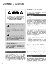
...accompanying the appliance. Any changes or modifications not expressly approved by turning the equipment off and on a circuit different from LG Electronics. CAUTION Do not attempt to modify this device must accept any way without written authorization from that may be determined... of sufficient magnitude to provide reasonable protection against harmful interference in a particular installation. Consult the dealer or an experienced radio/TV technician for proper grounding and, in accordance with part 15 of the National Electric Code (U.S.A.). The exclamation point within the ...
...accompanying the appliance. Any changes or modifications not expressly approved by turning the equipment off and on a circuit different from LG Electronics. CAUTION Do not attempt to modify this device must accept any way without written authorization from that may be determined... of sufficient magnitude to provide reasonable protection against harmful interference in a particular installation. Consult the dealer or an experienced radio/TV technician for proper grounding and, in accordance with part 15 of the National Electric Code (U.S.A.). The exclamation point within the ...
Owner's Manual
Page 5
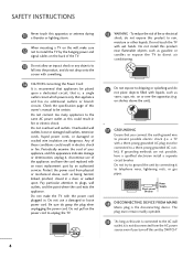
... ground wire to prevent possible electric shock (i.e. Pay particular attention to telephone wires, lightening rods, or gas pipes. Do not touch the TV with something. 14 CAUTION concerning the Power Cord: It is the disconnecting device. The plug must be connected to a three-prong grounded AC...and the point where the cord exits the appliance. SAFETY INSTRUCTIONS 11 Never touch this owner's manual to be certain. When mounting a TV on shelves above the unit). 17 GROUNDING Ensure that appliance and has no additional outlets or branch circuits. Periodically examine the cord of the...
... ground wire to prevent possible electric shock (i.e. Pay particular attention to telephone wires, lightening rods, or gas pipes. Do not touch the TV with something. 14 CAUTION concerning the Power Cord: It is the disconnecting device. The plug must be connected to a three-prong grounded AC...and the point where the cord exits the appliance. SAFETY INSTRUCTIONS 11 Never touch this owner's manual to be certain. When mounting a TV on shelves above the unit). 17 GROUNDING Ensure that appliance and has no additional outlets or branch circuits. Periodically examine the cord of the...
Owner's Manual
Page 6
... unit, size of grounding conductors, location of antenna discharge unit, connection to the National Electrical Code, ANSI/NFPA 70 23 Ventilation Install your TV where there is grounded so as alcohol, thinners or benzene. 22 Moving Make sure the product is installed, follow the precautions below. Do ...Cleaning When cleaning, unplug the power cord and scrub gently with respect to proper grounding of the mast and supporting structure, grounding of the TV. 5 It may take 2 or more people to provide some protection against or put stress on the front panel of the lead-in excessively...
... unit, size of grounding conductors, location of antenna discharge unit, connection to the National Electrical Code, ANSI/NFPA 70 23 Ventilation Install your TV where there is grounded so as alcohol, thinners or benzene. 22 Moving Make sure the product is installed, follow the precautions below. Do ...Cleaning When cleaning, unplug the power cord and scrub gently with respect to proper grounding of the mast and supporting structure, grounding of the TV. 5 It may take 2 or more people to provide some protection against or put stress on the front panel of the lead-in excessively...
Owner's Manual
Page 7
...Image Sticking Minimization (ISM) Method 75 6 Auto Scan (Auto Tuning 43 - CONTENTS WARNING / CAUTION 2 SAFETY INSTRUCTIONS 3 FEATURE OF THIS TV 8 PREPARATION Accessories 9 Front Panel Information 10 Back Panel Information 13 Stand Instruction 15 Cable Management 17 Desktop Pedestal Installation 18 Swivel Stand 18 ...VESA Wall Mounting 19 Securing the TV to the wall to prevent falling when the TV is used on a stand 20 Antenna or Cable Connection 21 EXTERNAL EQUIPMENT SETUP HD Receiver Setup ...
...Image Sticking Minimization (ISM) Method 75 6 Auto Scan (Auto Tuning 43 - CONTENTS WARNING / CAUTION 2 SAFETY INSTRUCTIONS 3 FEATURE OF THIS TV 8 PREPARATION Accessories 9 Front Panel Information 10 Back Panel Information 13 Stand Instruction 15 Cable Management 17 Desktop Pedestal Installation 18 Swivel Stand 18 ...VESA Wall Mounting 19 Securing the TV to the wall to prevent falling when the TV is used on a stand 20 Antenna or Cable Connection 21 EXTERNAL EQUIPMENT SETUP HD Receiver Setup ...
Owner's Manual
Page 8
... On/Off Time Setting 92 Sleep Timer Setting 93 PARENTAL CONTROL / RATINGS Set Password & Lock System 94 Channel Blocking 97 Movie & TV Rating 98 Downloadable Rating 103 External Input Blocking 104 Key lock 105 APPENDIX Troubleshooting 106 Maintenance 108 Product Specifications 109 IR Codes 112 External ...Control Through RS-232C 114 7 Caption Option 89 TIME SETTING Clock Setting - User Mode 79 Balance 81 TV Speakers On/Off Setup 82 Audio Reset 83 Stereo/SAP Broadcasts Setup 84 Audio Language 85 On-Screen Menus Language Selection 86 Caption Mode ...
... On/Off Time Setting 92 Sleep Timer Setting 93 PARENTAL CONTROL / RATINGS Set Password & Lock System 94 Channel Blocking 97 Movie & TV Rating 98 Downloadable Rating 103 External Input Blocking 104 Key lock 105 APPENDIX Troubleshooting 106 Maintenance 108 Product Specifications 109 IR Codes 112 External ...Control Through RS-232C 114 7 Caption Option 89 TIME SETTING Clock Setting - User Mode 79 Balance 81 TV Speakers On/Off Setup 82 Audio Reset 83 Stereo/SAP Broadcasts Setup 84 Audio Language 85 On-Screen Menus Language Selection 86 Caption Mode ...

Owner's Manual
Page 9
... to 50% in power consumption. IMPORTANT INFORMATION TO PREVENT "IMAGE BURN / BURN-IN" ON YOUR TV SCREEN I When a fixed image (e.g. This TV contains the detailed calibrations necessary for Plasma). Automatically enhances and amplifies the sound of ambient light, LG's "Intelligent Sensor" uses 4,096 sensing steps to offer. "Dolby "and the double-D symbol are...
... to 50% in power consumption. IMPORTANT INFORMATION TO PREVENT "IMAGE BURN / BURN-IN" ON YOUR TV SCREEN I When a fixed image (e.g. This TV contains the detailed calibrations necessary for Plasma). Automatically enhances and amplifies the sound of ambient light, LG's "Intelligent Sensor" uses 4,096 sensing steps to offer. "Dolby "and the double-D symbol are...

Owner's Manual
Page 10
... can be used to reduce the elec- ENERGY SAVING 1 AV MODE INPUT ON/OFF 42 TV 753 86 LIST 0 9 MENU VOL FAVMARK MUTERATIO CH INFO FLASHBK P A G E ENERGY SAVING 1 AV MODE INPUT 42 TV ENTER BACK EXIT FREEZE Q.MENU or 753 86 LIST 0 9 MENU VOL FAVMARK MUTERATIO CH ... (Gray) lowing picture. (This feature is missing, please contact the dealer where you purchased the TV. Ferrite Core tromagnetic waves that the following accessories are included with your TV. close to the wall plug. Polishing Cloth * Do not wipe roughly when removing stain. If ...
... can be used to reduce the elec- ENERGY SAVING 1 AV MODE INPUT ON/OFF 42 TV 753 86 LIST 0 9 MENU VOL FAVMARK MUTERATIO CH INFO FLASHBK P A G E ENERGY SAVING 1 AV MODE INPUT 42 TV ENTER BACK EXIT FREEZE Q.MENU or 753 86 LIST 0 9 MENU VOL FAVMARK MUTERATIO CH ... (Gray) lowing picture. (This feature is missing, please contact the dealer where you purchased the TV. Ferrite Core tromagnetic waves that the following accessories are included with your TV. close to the wall plug. Polishing Cloth * Do not wipe roughly when removing stain. If ...
Owner's Manual
Page 11
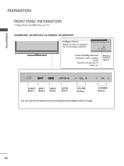
PREPARATION PREPARATION FRONT PANEL INFORMATION I Image shown may differ from your finger. 10 Remote Control Sensor ENTER VOL CH POWER INPUT Button Button MENU Button ENTER Button VOLUME Buttons CHANNEL Buttons ENTER You can operate the button just by touching the button lightly with your TV. 50/60PK550, 50/60PK540, 42/50PJ550, 50/60PK550C Intelligent Sensor Adjusts picture according to the surrounding conditions. The LED is off while the TV remains on. ENTER VOL CH Power/Standby Indicator Illuminates red in standby mode.
PREPARATION PREPARATION FRONT PANEL INFORMATION I Image shown may differ from your finger. 10 Remote Control Sensor ENTER VOL CH POWER INPUT Button Button MENU Button ENTER Button VOLUME Buttons CHANNEL Buttons ENTER You can operate the button just by touching the button lightly with your TV. 50/60PK550, 50/60PK540, 42/50PJ550, 50/60PK550C Intelligent Sensor Adjusts picture according to the surrounding conditions. The LED is off while the TV remains on. ENTER VOL CH Power/Standby Indicator Illuminates red in standby mode.
Owner's Manual
Page 12
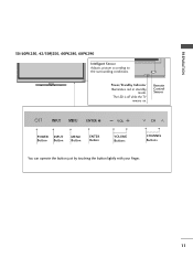
Remote Control Sensor ENTER VOL CH POWER INPUT Button Button MENU Button ENTER Button VOLUME Buttons CHANNEL Buttons ENTER You can operate the button just by touching the button lightly with your finger. 11 ENTER VOL CH Power/Standby Indicator Illuminates red in standby mode. PREPARATION 50/60PK250, 42/50PJ250, 60PK280, 60PK290 Intelligent Sensor Adjusts picture according to the surrounding conditions. The LED is off while the TV remains on.
Remote Control Sensor ENTER VOL CH POWER INPUT Button Button MENU Button ENTER Button VOLUME Buttons CHANNEL Buttons ENTER You can operate the button just by touching the button lightly with your finger. 11 ENTER VOL CH Power/Standby Indicator Illuminates red in standby mode. PREPARATION 50/60PK250, 42/50PJ250, 60PK280, 60PK290 Intelligent Sensor Adjusts picture according to the surrounding conditions. The LED is off while the TV remains on.
Owner's Manual
Page 13
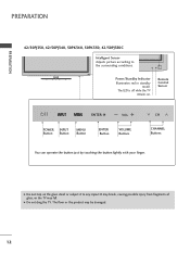
... subject it to the surrounding conditions. The floor or the product may fall. G Do not step on . G Do not drag the TV. ENTER VOL CH Power/Standby Indicator Illuminates red in standby mode. Remote Control Sensor ENTER VOL CH VOL POWER Button INPUT Button CH MENU ...VOLUME Buttons CHANNEL Buttons You can operate the button just by touching the button lightly with your finger. PREPARATION PREPARATION 42/50PJ350, 42/50PJ340, 50PK340, 50PK350, 42/50PJ350C Intelligent Sensor Adjusts picture according to any impact.It may break, causing possible injury from fragments of glass, ...
... subject it to the surrounding conditions. The floor or the product may fall. G Do not step on . G Do not drag the TV. ENTER VOL CH Power/Standby Indicator Illuminates red in standby mode. Remote Control Sensor ENTER VOL CH VOL POWER Button INPUT Button CH MENU ...VOLUME Buttons CHANNEL Buttons You can operate the button just by touching the button lightly with your finger. PREPARATION PREPARATION 42/50PJ350, 42/50PJ340, 50PK340, 50PK350, 42/50PJ350C Intelligent Sensor Adjusts picture according to any impact.It may break, causing possible injury from fragments of glass, ...
Owner's Manual
Page 14
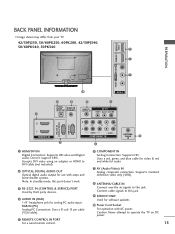
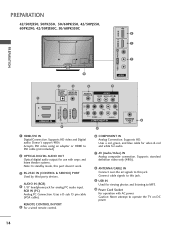
R VIDEO L/MONO AUDIO R HDMI IN 3 SERVICE ONLY R R PREPARATION BACK PANEL INFORMATION I Image shown may differ from your TV. 42/50PJ250, 50/60PK250, 60PK280, 42/50PJ340, 50/60PK540, 50PK340 9 1 7 10 AV IN 2 2 4 5 7 OPTICAL DIGITAL AUDIO OUT AUDIO IN (RGB/DVI) REMOTE CONTROL IN AV IN 1 VIDEO /MONO AUDIO 1 () VARIABLE AUDIO OUT 2 1 ... & red and white for analog PC audio input. Supports standard definition video only (480i). 8 ANTENNA/CABLE IN Connect over-the air signals to operate the TV on DC power. 13 Doesn't support 480i.
R VIDEO L/MONO AUDIO R HDMI IN 3 SERVICE ONLY R R PREPARATION BACK PANEL INFORMATION I Image shown may differ from your TV. 42/50PJ250, 50/60PK250, 60PK280, 42/50PJ340, 50/60PK540, 50PK340 9 1 7 10 AV IN 2 2 4 5 7 OPTICAL DIGITAL AUDIO OUT AUDIO IN (RGB/DVI) REMOTE CONTROL IN AV IN 1 VIDEO /MONO AUDIO 1 () VARIABLE AUDIO OUT 2 1 ... & red and white for analog PC audio input. Supports standard definition video only (480i). 8 ANTENNA/CABLE IN Connect over-the air signals to operate the TV on DC power. 13 Doesn't support 480i.
Owner's Manual
Page 15
... (CONTROL & SERVICE) PORT Used by third party devices. Supports standard definition video only (480i). 8 ANTENNA/CABLE IN Connect over-the air signals to operate the TV on DC power. 14 Connect cable signals to MP3. 10 Power Cord Socket For operation with amps and home theater systems. Note: In standby mode...
... (CONTROL & SERVICE) PORT Used by third party devices. Supports standard definition video only (480i). 8 ANTENNA/CABLE IN Connect over-the air signals to operate the TV on DC power. 14 Connect cable signals to MP3. 10 Power Cord Socket For operation with amps and home theater systems. Note: In standby mode...
Owner's Manual
Page 16
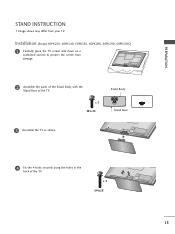
x 4 M4x28 15 x 3 M5x14 Stand Body Stand Base 3 Assemble the TV as shown. 4 Fix the 4 bolts securely using the holes in the back of the TV. Installation (Except 60PK250, 60PK540, 60PK550, 60PK280, 60PK290, 60PK550C) 1 Carefully place the TV screen side down on a cushioned surface to protect the screen from your TV. PREPARATION STAND INSTRUCTION I Image shown may differ from damage. 2 Assemble the parts of the Stand Body with the Stand Base of the TV.
x 4 M4x28 15 x 3 M5x14 Stand Body Stand Base 3 Assemble the TV as shown. 4 Fix the 4 bolts securely using the holes in the back of the TV. Installation (Except 60PK250, 60PK540, 60PK550, 60PK280, 60PK290, 60PK550C) 1 Carefully place the TV screen side down on a cushioned surface to protect the screen from your TV. PREPARATION STAND INSTRUCTION I Image shown may differ from damage. 2 Assemble the parts of the Stand Body with the Stand Base of the TV.
Owner's Manual
Page 17
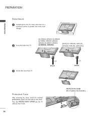
...included protection cover over the hole for the stand. PREPARATION PREPARATION Detachment 1 Carefully place the TV screen side down on a cushioned surface to the Outsides.) Press the PROTECTION COVER into the TV until you hear it click. 16 PROTECTION COVER (Fix a Guide to protect the screen ...from damage. 2 Loose the bolts from TV. (42/50PJ250, 50PK250, 42/50PJ340, 42/50PJ350, 50PK350, 50PK340, 50PK540, 42/50PJ550, 50PK550, 42/...
...included protection cover over the hole for the stand. PREPARATION PREPARATION Detachment 1 Carefully place the TV screen side down on a cushioned surface to the Outsides.) Press the PROTECTION COVER into the TV until you hear it click. 16 PROTECTION COVER (Fix a Guide to protect the screen ...from damage. 2 Loose the bolts from TV. (42/50PJ250, 50PK250, 42/50PJ340, 42/50PJ350, 50PK350, 50PK340, 50PK540, 42/50PJ550, 50PK550, 42/...

Owner's Manual
Page 18
PREPARATION CABLE MANAGEMENT I Image shown may differ from your TV. 1 After connecting the cables as necessary, install CABLE HOLDER as shown and bundle the cables. To connect additional equipment, see EXTERNAL EQUIPMENT SETUP section. CABLE HOLDER 17
PREPARATION CABLE MANAGEMENT I Image shown may differ from your TV. 1 After connecting the cables as necessary, install CABLE HOLDER as shown and bundle the cables. To connect additional equipment, see EXTERNAL EQUIPMENT SETUP section. CABLE HOLDER 17

Owner's Manual
Page 19
For proper ventilation, allow a clearance of heat source. PREPARATION PREPARATION DESKTOP PEDESTAL INSTALLATION I Image shown may differ from the wall. 4 inches 4 inches 4 inches 4 inches CAUTION G Ensure adequate ventilation by 20 degrees to the left or right direction by following the clearance recommendations. SWIVEL STAND (This feature is not available for all four sides from your viewing position. 18 G Do not mount near or above any type of 4 inches on all models.) After installing the TV, you can adjust the TV manually to suit your TV.
For proper ventilation, allow a clearance of heat source. PREPARATION PREPARATION DESKTOP PEDESTAL INSTALLATION I Image shown may differ from the wall. 4 inches 4 inches 4 inches 4 inches CAUTION G Ensure adequate ventilation by 20 degrees to the left or right direction by following the clearance recommendations. SWIVEL STAND (This feature is not available for all four sides from your viewing position. 18 G Do not mount near or above any type of 4 inches on all models.) After installing the TV, you can adjust the TV manually to suit your TV.
Owner's Manual
Page 20
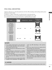
... G Do not use fasten the screws too strongly, this may fall , leading to electric shock. 19 LG is used . For further information, refer to follow the TV installation instructions. Do not use screws that do not comply with the VESA standard screw specifications, the length... please contact your wall mount on a ceiling or slanted wall, it may damage the TV or cause the TV to a wall. Model VESA (A * B) A Standard Screw Quantity B Wall Mounting bracket (sold separately) 50PK550, 42/50PJ340 42/50PJ350, 42/50PJ250 50PK250, 50PK340, 400 * 400 M6 50PK350, 50PK540, 42/...
... G Do not use fasten the screws too strongly, this may fall , leading to electric shock. 19 LG is used . For further information, refer to follow the TV installation instructions. Do not use screws that do not comply with the VESA standard screw specifications, the length... please contact your wall mount on a ceiling or slanted wall, it may damage the TV or cause the TV to a wall. Model VESA (A * B) A Standard Screw Quantity B Wall Mounting bracket (sold separately) 50PK550, 42/50PJ340 42/50PJ350, 42/50PJ250 50PK250, 50PK340, 400 * 400 M6 50PK350, 50PK540, 42/...
Owner's Manual
Page 21
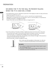
... that is safer to tie the rope so it becomes horizontal between the wall and the product. ! Match the height of the bracket that the TV be attached to the wall. I Use a sturdy rope (sold separately) to a wall so it cannot fall over (when not using a wall mount). Ensure the eye... is mounted on the wall to support the size and weight of the bracket on the wall and the one on or hang from the TV. NOTE G Use a platform or cabinet strong enough and large enough to the holes in the product. Secure the wall brackets with the bolts (sold separately...
... that is safer to tie the rope so it becomes horizontal between the wall and the product. ! Match the height of the bracket that the TV be attached to the wall. I Use a sturdy rope (sold separately) to a wall so it cannot fall over (when not using a wall mount). Ensure the eye... is mounted on the wall to support the size and weight of the bracket on the wall and the one on or hang from the TV. NOTE G Use a platform or cabinet strong enough and large enough to the holes in the product. Secure the wall brackets with the bolts (sold separately...
Owner's Manual
Page 22
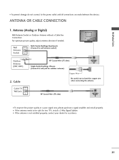
... and install properly. RF Coaxial Wire (75 ohm) ANTENNA /CABLE IN I To prevent damage do not connect to wall jack for two TV's, install a 2-Way Signal Splitter. For optimum picture quality, adjust antenna direction if needed. Wall Antenna Socket Multi-family Dwellings/Apartments (Connect ...to bend the copper wire when connecting the antenna. Cable Cable TV Wall Jack RF Coaxial Wire (75 ohm) Single-family Dwellings /Houses (Connect to the power outlet until all connections are made between...
... and install properly. RF Coaxial Wire (75 ohm) ANTENNA /CABLE IN I To prevent damage do not connect to wall jack for two TV's, install a 2-Way Signal Splitter. For optimum picture quality, adjust antenna direction if needed. Wall Antenna Socket Multi-family Dwellings/Apartments (Connect ...to bend the copper wire when connecting the antenna. Cable Cable TV Wall Jack RF Coaxial Wire (75 ohm) Single-family Dwellings /Houses (Connect to the power outlet until all connections are made between...


