Owner's Manual
Page 15
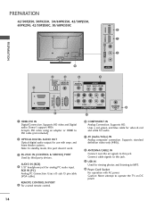
... white for use with AC power. Supports HD video and Digital audio. Connect cable signals to DVI cable (not included) 2 OPTICAL DIGITAL AUDIO OUT Optical digital audio output for audio. 7 AV (Audio/Video) IN Analog composite connection. R VIDEO L/MONO AUDIO R HDMI IN 3 USB IN R R PREPARATION 42/50PJ350, 50PK350, 50/60PK550, 42/50PJ550, 60PK290, 42/50PJ350C, 50/60PK550C 9 1 PREPARATION...
... white for use with AC power. Supports HD video and Digital audio. Connect cable signals to DVI cable (not included) 2 OPTICAL DIGITAL AUDIO OUT Optical digital audio output for audio. 7 AV (Audio/Video) IN Analog composite connection. R VIDEO L/MONO AUDIO R HDMI IN 3 USB IN R R PREPARATION 42/50PJ350, 50PK350, 50/60PK550, 42/50PJ550, 60PK290, 42/50PJ350C, 50/60PK550C 9 1 PREPARATION...
Training Manual
Page 34
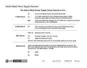
Switch Mode Power Supply Overview The Switch Mode Power Supply Board Outputs to the Z-SUS Board. Use "Full White Raster" 100 IRE VS VR901 VA VR502 34 July 2010 50PJ350 Plasma Main Board STBY 5V Microprocessor Circuits 17V Audio B+ Supply, Tuner B+ Circuits 5V Signal Processing Circuits Also AC_Det (if missing, shuts of TV in...
Switch Mode Power Supply Overview The Switch Mode Power Supply Board Outputs to the Z-SUS Board. Use "Full White Raster" 100 IRE VS VR901 VA VR502 34 July 2010 50PJ350 Plasma Main Board STBY 5V Microprocessor Circuits 17V Audio B+ Supply, Tuner B+ Circuits 5V Signal Processing Circuits Also AC_Det (if missing, shuts of TV in...
Training Manual
Page 37
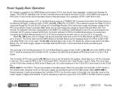
... 8 of the SMPS if the Main board is floated (opened), it is not used for Microprocessor (IC1) operation (STBY 3.46V RUN 5.14V). The 17V Audio supply outputs to the Main board at P813 pins 1 and 2 and used . The next step is for the Controller chip on the back of P813: This pin... is output at P812 to the Y-SUS board P210. (VA pins 6 and 7 and VS pins 1 and 2). When AUTO GND is suspect. 37 July 2010 50PJ350 Plasma A load is necessary to perform a good test of P813 (2.85V STBY and 4.90V...
... 8 of the SMPS if the Main board is floated (opened), it is not used for Microprocessor (IC1) operation (STBY 3.46V RUN 5.14V). The 17V Audio supply outputs to the Main board at P813 pins 1 and 2 and used . The next step is for the Controller chip on the back of P813: This pin... is output at P812 to the Y-SUS board P210. (VA pins 6 and 7 and VS pins 1 and 2). When AUTO GND is suspect. 37 July 2010 50PJ350 Plasma A load is necessary to perform a good test of P813 (2.85V STBY and 4.90V...
Training Manual
Page 107
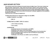
... provides VSB, 8VSB and QAM is also where the television's software upgrades are accomplished through the USB input. It also receives all input, outputs. This board is located on the main board. This board has no mechanical adjustments. The Main Board Receives its operational voltage from the SMPS.... • Distributes Key 1 and Key 2 to the Front IR Board then to the Front IR Board. 107 July 2010 50PJ350 Plasma This board contains the Microprocessor, Audio section, video section and all input signals and processes them to be delivered to the Control board via SCL/SDA). • ...
... provides VSB, 8VSB and QAM is also where the television's software upgrades are accomplished through the USB input. It also receives all input, outputs. This board is located on the main board. This board has no mechanical adjustments. The Main Board Receives its operational voltage from the SMPS.... • Distributes Key 1 and Key 2 to the Front IR Board then to the Front IR Board. 107 July 2010 50PJ350 Plasma This board contains the Microprocessor, Audio section, video section and all input signals and processes them to be delivered to the Control board via SCL/SDA). • ...


