

Owner's Manual
Page 4
... servicing to qualified service personnel. Servicing is required when the apparatus has been damaged in accordance with the manufacturer's instructions. 8 Use only with the cart, stand, tripod, bracket, or table specified by the manufacturer. 3 Do not block any ventilation openings. SAFETY INSTRUCTIONS IMPORTANT SAFETY INSTRUCTIONS Read these instructions. Follow all instructions...
... servicing to qualified service personnel. Servicing is required when the apparatus has been damaged in accordance with the manufacturer's instructions. 8 Use only with the cart, stand, tripod, bracket, or table specified by the manufacturer. 3 Do not block any ventilation openings. SAFETY INSTRUCTIONS IMPORTANT SAFETY INSTRUCTIONS Read these instructions. Follow all instructions...
Owner's Manual
Page 7
... VESA Wall Mounting 19 Securing the TV to the wall to prevent falling when the TV is used on a stand 20 Antenna or Cable Connection 21 EXTERNAL EQUIPMENT SETUP HD Receiver Setup 22 DVD Setup 25 VCR Setup 27 Other A/V Source Setup 28 USB Connection ...
... VESA Wall Mounting 19 Securing the TV to the wall to prevent falling when the TV is used on a stand 20 Antenna or Cable Connection 21 EXTERNAL EQUIPMENT SETUP HD Receiver Setup 22 DVD Setup 25 VCR Setup 27 Other A/V Source Setup 28 USB Connection ...

Owner's Manual
Page 10
...- The ferrite core can be used to AUDIO IN(RGB/DVI) jack available for all on the exterior only with the (Black) TV. available for stand assembly (Refer to the wall plug. netic waves in the fol- (Gray) lowing picture. (This feature is missing, please contact the dealer where you purchased...
...- The ferrite core can be used to AUDIO IN(RGB/DVI) jack available for all on the exterior only with the (Black) TV. available for stand assembly (Refer to the wall plug. netic waves in the fol- (Gray) lowing picture. (This feature is missing, please contact the dealer where you purchased...
Owner's Manual
Page 13
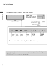
ENTER VOL CH Power/Standby Indicator Illuminates red in standby mode. G Do not drag the TV. PREPARATION PREPARATION 42/50PJ350, 42/50PJ340, 50PK340, 50PK350, 42/50PJ350C Intelligent Sensor Adjusts picture according to any impact.It may break, causing possible injury from fragments of glass, or the ...TV may be damaged. 12 G Do not step on . The LED is off while the TV remains on the glass stand or subject it to the surrounding conditions. Remote Control Sensor ENTER VOL CH VOL POWER Button INPUT Button CH MENU Button ENTER Button VOLUME Buttons...
ENTER VOL CH Power/Standby Indicator Illuminates red in standby mode. G Do not drag the TV. PREPARATION PREPARATION 42/50PJ350, 42/50PJ340, 50PK340, 50PK350, 42/50PJ350C Intelligent Sensor Adjusts picture according to any impact.It may break, causing possible injury from fragments of glass, or the ...TV may be damaged. 12 G Do not step on . The LED is off while the TV remains on the glass stand or subject it to the surrounding conditions. Remote Control Sensor ENTER VOL CH VOL POWER Button INPUT Button CH MENU Button ENTER Button VOLUME Buttons...
Owner's Manual
Page 16
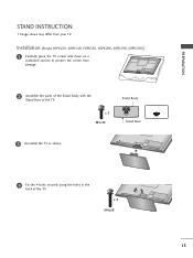
Installation (Except 60PK250, 60PK540, 60PK550, 60PK280, 60PK290, 60PK550C) 1 Carefully place the TV screen side down on a cushioned surface to protect the screen from your TV. x 3 M5x14 Stand Body Stand Base 3 Assemble the TV as shown. 4 Fix the 4 bolts securely using the holes in the back of the TV. PREPARATION STAND INSTRUCTION I Image shown may differ from damage. 2 Assemble the parts of the Stand Body with the Stand Base of the TV. x 4 M4x28 15
Installation (Except 60PK250, 60PK540, 60PK550, 60PK280, 60PK290, 60PK550C) 1 Carefully place the TV screen side down on a cushioned surface to protect the screen from your TV. x 3 M5x14 Stand Body Stand Base 3 Assemble the TV as shown. 4 Fix the 4 bolts securely using the holes in the back of the TV. PREPARATION STAND INSTRUCTION I Image shown may differ from damage. 2 Assemble the parts of the Stand Body with the Stand Base of the TV. x 4 M4x28 15
Owner's Manual
Page 17
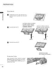
...Loose the bolts from TV. (42/50PJ250, 50PK250, 42/50PJ340, 42/50PJ350, 50PK350, 50PK340, 50PK540, 42/50PJ550, 50PK550, 42/50PJ350C, 50PK550C) (60PK250, 60PK540, 60PK550, 60PK280, 60PK290, 60PK550C) 3 Detach the stand from TV. PREPARATION PREPARATION Detachment 1 Carefully place the TV ...screen side down on a cushioned surface to the Outsides.) x 4 M4x28 x 5 M4x30 Protection Cover After removing the stand, install the included protection cover over the hole ...
...Loose the bolts from TV. (42/50PJ250, 50PK250, 42/50PJ340, 42/50PJ350, 50PK350, 50PK340, 50PK540, 42/50PJ550, 50PK550, 42/50PJ350C, 50PK550C) (60PK250, 60PK540, 60PK550, 60PK280, 60PK290, 60PK550C) 3 Detach the stand from TV. PREPARATION PREPARATION Detachment 1 Carefully place the TV ...screen side down on a cushioned surface to the Outsides.) x 4 M4x28 x 5 M4x30 Protection Cover After removing the stand, install the included protection cover over the hole ...

Owner's Manual
Page 19
PREPARATION PREPARATION DESKTOP PEDESTAL INSTALLATION I Image shown may differ from the wall. 4 inches 4 inches 4 inches 4 inches CAUTION G Ensure adequate ventilation by 20 degrees to the left or right direction by following the clearance recommendations. SWIVEL STAND (This feature is not available for all four sides from your viewing position. 18 For proper ventilation, allow a clearance of heat source. G Do not mount near or above any type of 4 inches on all models.) After installing the TV, you can adjust the TV manually to suit your TV.
PREPARATION PREPARATION DESKTOP PEDESTAL INSTALLATION I Image shown may differ from the wall. 4 inches 4 inches 4 inches 4 inches CAUTION G Ensure adequate ventilation by 20 degrees to the left or right direction by following the clearance recommendations. SWIVEL STAND (This feature is not available for all four sides from your viewing position. 18 For proper ventilation, allow a clearance of heat source. G Do not mount near or above any type of 4 inches on all models.) After installing the TV, you can adjust the TV manually to suit your TV.
Owner's Manual
Page 21
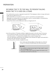
... as shown in the picture. * If your TV. PREPARATION PREPARATION SECURING THE TV TO THE WALL TO PREVENT FALLING WHEN THE TV IS USED ON A STAND I You should purchase necessary components to prevent the TV from tipping over if pushed backwards.
... as shown in the picture. * If your TV. PREPARATION PREPARATION SECURING THE TV TO THE WALL TO PREVENT FALLING WHEN THE TV IS USED ON A STAND I You should purchase necessary components to prevent the TV from tipping over if pushed backwards.
Owner's Manual
Page 110
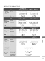
...stand Without stand Weight With stand Without stand MODEL Dimensions (Width x Height x Depth) With stand Without stand Weight With stand Without stand MODEL Dimensions (Width x Height x Depth) With stand Without stand Weight With stand Without stand MODEL Dimensions (Width x Height x Depth) With stand Without stand Weight With stand Without stand....4 mm x 720.9 mm x 55.3 mm (46.1inches x 28.3 inch x 2.1 inch) 30kg (66.1 lb) 27.6 kg (60.8 lb) 50PJ340 (50PJ340-UB, 50PJ340-UC, 50PJ340-UH) 1171.4 mm x 781.8 mm x 309.7 mm (46.1inches x 30.7 inch x 12.1 inch) 1171.4 mm x 720.9 mm x 55...
...stand Without stand Weight With stand Without stand MODEL Dimensions (Width x Height x Depth) With stand Without stand Weight With stand Without stand MODEL Dimensions (Width x Height x Depth) With stand Without stand Weight With stand Without stand MODEL Dimensions (Width x Height x Depth) With stand Without stand Weight With stand Without stand....4 mm x 720.9 mm x 55.3 mm (46.1inches x 28.3 inch x 2.1 inch) 30kg (66.1 lb) 27.6 kg (60.8 lb) 50PJ340 (50PJ340-UB, 50PJ340-UC, 50PJ340-UH) 1171.4 mm x 781.8 mm x 309.7 mm (46.1inches x 30.7 inch x 12.1 inch) 1171.4 mm x 720.9 mm x 55...
Owner's Manual
Page 111
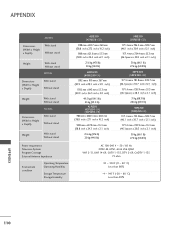
APPENDIX MODEL Dimensions (Width x Height x Depth) With stand Without stand Weight With stand Without stand MODEL Dimensions (Width x Height x Depth) With stand Without stand Weight With stand Without stand MODEL Dimensions (Width x Height x Depth) With stand Without stand Weight With stand Without stand 42PJ550 (42PJ550-UD) 988 mm x 692.7 mm x 260 mm (38.8 inch x 27.2 inch x 10.2 inch) 988 mm x 621.8 mm x 55...
APPENDIX MODEL Dimensions (Width x Height x Depth) With stand Without stand Weight With stand Without stand MODEL Dimensions (Width x Height x Depth) With stand Without stand Weight With stand Without stand MODEL Dimensions (Width x Height x Depth) With stand Without stand Weight With stand Without stand 42PJ550 (42PJ550-UD) 988 mm x 692.7 mm x 260 mm (38.8 inch x 27.2 inch x 10.2 inch) 988 mm x 621.8 mm x 55...
Owner's Manual
Page 112
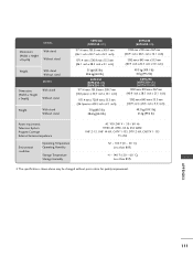
MODEL Dimensions (Width x Height x Depth) With stand Without stand Weight With stand Without stand MODEL Dimensions (Width x Height x Depth) With stand Without stand Weight With stand Without stand 50PK350 (50PK350-UC) 1171.4 mm x 781.8 mm x 309.7 mm (46.1 inch x 30.7 inch x 12.1 inch) 1171.4 mm x 720.9 mm x 55.3 mm (46.1 inch x 28.3 inch x 2.1 ...
MODEL Dimensions (Width x Height x Depth) With stand Without stand Weight With stand Without stand MODEL Dimensions (Width x Height x Depth) With stand Without stand Weight With stand Without stand 50PK350 (50PK350-UC) 1171.4 mm x 781.8 mm x 309.7 mm (46.1 inch x 30.7 inch x 12.1 inch) 1171.4 mm x 720.9 mm x 55.3 mm (46.1 inch x 28.3 inch x 2.1 ...
Training Manual
Page 13
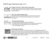
... to be viewed at the same price as less-efficient models. Less energy means you pay less on Intelligent Sensor). Draws less than 1 Watt in stand by. 13 July 2010 50PJ350 Plasma 50PJ350 Logo Familiarization Page 3 of the human voice frequency range to quickly switch between common settings. Save Energy, Save...
... to be viewed at the same price as less-efficient models. Less energy means you pay less on Intelligent Sensor). Draws less than 1 Watt in stand by. 13 July 2010 50PJ350 Plasma 50PJ350 Logo Familiarization Page 3 of the human voice frequency range to quickly switch between common settings. Save Energy, Save...
Training Manual
Page 17
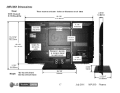
Label 2-3/8" 60.96mm Weight: 78.5 lbs with Stand 60.8 lbs without Stand 15-3/4" 400mm Remove 4 screws to remove stand for wall mount 20-7/8" 530mm 17 7-3/8" 187.2mm 2-3/4" 70mm 12-3/16" 309.88mm July 2010 50PJ350 Plasma 50PJ350 Dimensions Power: 340W (Typical) 0.1W (Stand-By) There must be at least 4 inches of Clearance on all sides 46-1/8" 1170.94mm 15-3/16" 385.8mm 15-3/4" 400mm 5-1/4" 133.6mm 2-3/16" 55.88mm 30-13/16" 782.32mm 28-3/8" 721.36mm Model No. Serial No.
Label 2-3/8" 60.96mm Weight: 78.5 lbs with Stand 60.8 lbs without Stand 15-3/4" 400mm Remove 4 screws to remove stand for wall mount 20-7/8" 530mm 17 7-3/8" 187.2mm 2-3/4" 70mm 12-3/16" 309.88mm July 2010 50PJ350 Plasma 50PJ350 Dimensions Power: 340W (Typical) 0.1W (Stand-By) There must be at least 4 inches of Clearance on all sides 46-1/8" 1170.94mm 15-3/16" 385.8mm 15-3/4" 400mm 5-1/4" 133.6mm 2-3/16" 55.88mm 30-13/16" 782.32mm 28-3/8" 721.36mm Model No. Serial No.
Training Manual
Page 19
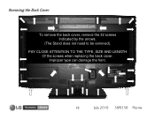
PAY CLOSE ATTENTION TO THE TYPE, SIZE AND LENGTH Of the screws when replacing the back cover. Improper type can damage the front. 19 July 2010 50PJ350 Plasma Removing the Back Cover To remove the back cover, remove the 32 screws Indicated by the arrows. (The Stand does not need to be removed).
PAY CLOSE ATTENTION TO THE TYPE, SIZE AND LENGTH Of the screws when replacing the back cover. Improper type can damage the front. 19 July 2010 50PJ350 Plasma Removing the Back Cover To remove the back cover, remove the 32 screws Indicated by the arrows. (The Stand does not need to be removed).
Training Manual
Page 22
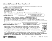
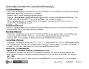
... does not come with these collars. Remove the Y-Drive Board. Remove the Y-SUS board. When replacing, be sure to the left. Lift up on board stand-offs that act as shock absorbers. When replacing, be sure to static failure. Collar Note: Y-SUS, Z-SUS and Y-Drive boards are mounted on the locking...
... does not come with these collars. Remove the Y-Drive Board. Remove the Y-SUS board. When replacing, be sure to the left. Lift up on board stand-offs that act as shock absorbers. When replacing, be sure to static failure. Collar Note: Y-SUS, Z-SUS and Y-Drive boards are mounted on the locking...
Training Manual
Page 23
... the board in the Z-SUB board. Z-SUB Board Removal Remove the two screws in place. Remove the board. Lift up slightly to clear the screw stand-offs and pull the Z-SUS to the panel. Remove the two screws in place. Control Board Removal Disconnect the following connectors: P12 LVDS, P111 Ribbon...
... the board in the Z-SUB board. Z-SUB Board Removal Remove the two screws in place. Remove the board. Lift up slightly to clear the screw stand-offs and pull the Z-SUS to the panel. Remove the two screws in place. Control Board Removal Disconnect the following connectors: P12 LVDS, P111 Ribbon...
Training Manual
Page 24
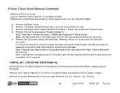
... / Vs / VScan / -VY / Z-Drive. 24 July 2010 50PJ350 Plasma Also, note that must also be removed. Reassemble in place. a) Remove the Back Cover. b) Remove the Stand (4 Stand Screws were removed during back removal). Note: There are two large pieces of conductive tape on the right side of the Right X Board that there... in reverse order. X Drive Circuit Board Removal Continued Make sure AC is removed. Make sure to clear the connector wires on a padded surface. c) Remove the Stand Metal Support Bracket (5 Screws) 2 Plastic tap thread and 3 Metal thread.
... / Vs / VScan / -VY / Z-Drive. 24 July 2010 50PJ350 Plasma Also, note that must also be removed. Reassemble in place. a) Remove the Back Cover. b) Remove the Stand (4 Stand Screws were removed during back removal). Note: There are two large pieces of conductive tape on the right side of the Right X Board that there... in reverse order. X Drive Circuit Board Removal Continued Make sure AC is removed. Make sure to clear the connector wires on a padded surface. c) Remove the Stand Metal Support Bracket (5 Screws) 2 Plastic tap thread and 3 Metal thread.
Training Manual
Page 25
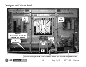
Getting to touch energized circuits. 25 July 2010 50PJ350 Plasma Do not allow to the X Circuit Boards D Left With Stand removed C D Right Warning: Never run the TV with the TCP Heat Sink removed E Heat Sink Ground Wire C B Warning Shorting Hazard: Conductive Tape.
Getting to touch energized circuits. 25 July 2010 50PJ350 Plasma Do not allow to the X Circuit Boards D Left With Stand removed C D Right Warning: Never run the TV with the TCP Heat Sink removed E Heat Sink Ground Wire C B Warning Shorting Hazard: Conductive Tape.
Training Manual
Page 30
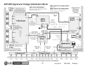
... CONTROL Board P101 Error Com SMPS Turn On Commands RL_ON Vs 17V, +5V, AC Det Z-SUS Board P2 FPCs P101 M_On M5V, Va, Vs P102 Stand By: STB +5 Run: AC Det +5, 17V 16V / M5V Z Drive Control P1 Signals P3 Z-SUB P7 Board P202 FPCs P203 P205 P212 Y Drive Floating Gnd (FG...
... CONTROL Board P101 Error Com SMPS Turn On Commands RL_ON Vs 17V, +5V, AC Det Z-SUS Board P2 FPCs P101 M_On M5V, Va, Vs P102 Stand By: STB +5 Run: AC Det +5, 17V 16V / M5V Z Drive Control P1 Signals P3 Z-SUB P7 Board P202 FPCs P203 P205 P212 Y Drive Floating Gnd (FG...
Training Manual
Page 35
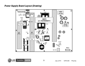
Power Supply Board Layout (Drawing) P812 VA TP VS TP F801 4A 250V Stand-By: 0.9V Run: 388V VS and VA TP ZD803 D805 T901 SMPS p/n: EAY60968701 T902 VR901 VS Adj VR502 VA Adj ZD302 D609 ZD401 D601 D307 ZD301 ZD303 D601 D303 ZD101 D305 Stand-By: 1.5V Run: 388V L601 D308 D309 D306 D302 F302 2.5A 250V T301 D103 D301 L602 F101 10A 250V SC101 P813 35 July 2010 50PJ350 Plasma
Power Supply Board Layout (Drawing) P812 VA TP VS TP F801 4A 250V Stand-By: 0.9V Run: 388V VS and VA TP ZD803 D805 T901 SMPS p/n: EAY60968701 T902 VR901 VS Adj VR502 VA Adj ZD302 D609 ZD401 D601 D307 ZD301 ZD303 D601 D303 ZD101 D305 Stand-By: 1.5V Run: 388V L601 D308 D309 D306 D302 F302 2.5A 250V T301 D103 D301 L602 F101 10A 250V SC101 P813 35 July 2010 50PJ350 Plasma


