

Owner's Manual
Page 45
... Move Enter F DTV G Select channel type and RF-channel number. Use the password you can store is subject to change depending on -screen signal strength monitor to see the quality of maximum channel you want to add or delete. I The TV will ask for a password if parental control has been activated...
... Move Enter F DTV G Select channel type and RF-channel number. Use the password you can store is subject to change depending on -screen signal strength monitor to see the quality of maximum channel you want to add or delete. I The TV will ask for a password if parental control has been activated...
Training Manual
Page 37
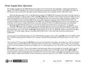
...) called RL_ON at Pin 15 of the A/C Line and routed to the Controller (IC701) where it outputs at P813 Pin 17 which is sensed and monitored by the Controller IC701, turning on the Y-SUS then routed out P203 to the Main board at Connector SC101 from the Main board. The 17V...
...) called RL_ON at Pin 15 of the A/C Line and routed to the Controller (IC701) where it outputs at P813 Pin 17 which is sensed and monitored by the Controller IC701, turning on the Y-SUS then routed out P203 to the Main board at Connector SC101 from the Main board. The 17V...
Training Manual
Page 42
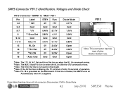
.... DVM in this line is floated, the SMPS turns on bottom row. a Note: The 17V, 5V, AC_Det and Error Det turn on when the M_On (Monitor On) command arrives. Odd on Automatically when AC is Missing, the TV will shut off after 10 seconds of pins. e Note: Pin 18 is not...
.... DVM in this line is floated, the SMPS turns on bottom row. a Note: The 17V, 5V, AC_Det and Error Det turn on when the M_On (Monitor On) command arrives. Odd on Automatically when AC is Missing, the TV will shut off after 10 seconds of pins. e Note: Pin 18 is not...

Training Manual
Page 92
... together. Example of these Signals would confirm the failure is delivered in 12 bit LVDS format. Their presence can be confirmed with the Oscilloscope by monitoring the LVDS signals with SMPTE Color Bar input. Pins 9~10 and 22~23 are referred to as Low Voltage Differential Signals or LVDS. P121 LVDS...
... together. Example of these Signals would confirm the failure is delivered in 12 bit LVDS format. Their presence can be confirmed with the Oscilloscope by monitoring the LVDS signals with SMPTE Color Bar input. Pins 9~10 and 22~23 are referred to as Low Voltage Differential Signals or LVDS. P121 LVDS...


