

Owner's Manual
Page 55
For 42/50PJ350, 50PK350, 50/60PK550, 42/50PJ550, 60PK290,42/50PJ350C models, 50/60PK550C ENTRY MODES When ... or unplug the USB device when the connected USB storage device is not offered by USB maker. G Please connect power to the USB connector holder of a storage device formatted as a FAT16, FAT32 or NTFS file system provided with ...memory stick and the other end to avoid losing the USB memory stick, use a USB storage device which requires an external power supply. G Please connect a USB storage device with more than the recommended capacity may not be damaged. NOTE G In order...
For 42/50PJ350, 50PK350, 50/60PK550, 42/50PJ550, 60PK290,42/50PJ350C models, 50/60PK550C ENTRY MODES When ... or unplug the USB device when the connected USB storage device is not offered by USB maker. G Please connect power to the USB connector holder of a storage device formatted as a FAT16, FAT32 or NTFS file system provided with ...memory stick and the other end to avoid losing the USB memory stick, use a USB storage device which requires an external power supply. G Please connect a USB storage device with more than the recommended capacity may not be damaged. NOTE G In order...

Training Manual
Page 2
...; Control Board • X Drive Boards (3) • Main Board • Interconnect Diagram: 11X17 Foldout Section used as a quick reference sheet. 2 July 2010 50PJ350 Plasma OUTLINE Overview of : • Switch Mode Power Supply No VS On command input to SMPS • Y-SUS Board Delivers Logic Signals and FG5V to be Discussed Preliminary: Contact Information, Preliminary...
...; Control Board • X Drive Boards (3) • Main Board • Interconnect Diagram: 11X17 Foldout Section used as a quick reference sheet. 2 July 2010 50PJ350 Plasma OUTLINE Overview of : • Switch Mode Power Supply No VS On command input to SMPS • Y-SUS Board Delivers Logic Signals and FG5V to be Discussed Preliminary: Contact Information, Preliminary...
Training Manual
Page 7
... thinner cabinet assemblies and mounts. Example: Y-SUS or Y-Drive Board Failure, Mal-discharge on the Power Supply, Y-SUS and Z-SUS Boards. 3. The PDP Module must be Considered 1. Exercise care when making adjustments on screen, etc. 7 July 2010 50PJ350 Plasma Check details of lost screws and other metal objects to prevent costly short circuits...
... thinner cabinet assemblies and mounts. Example: Y-SUS or Y-Drive Board Failure, Mal-discharge on the Power Supply, Y-SUS and Z-SUS Boards. 3. The PDP Module must be Considered 1. Exercise care when making adjustments on screen, etc. 7 July 2010 50PJ350 Plasma Check details of lost screws and other metal objects to prevent costly short circuits...

Training Manual
Page 8
Look for burned parts and check for proper levels. Frequency of the front Power LEDs may give off a distinct odor. Observation of power supplies will change with the Oscilloscope to make sure to correct the problem. Be careful of ESD and make a final determination of an ... circuits could be sure they are noise free. Capacitors will be the DC Supply Voltages to the Customer. 8 July 2010 50PJ350 Plasma Look for correct Amplitude Phasing and Timing of the signals. Always confirm the supplies are missing check the resistance for possible short circuits. • Isolate To ...
Look for burned parts and check for proper levels. Frequency of the front Power LEDs may give off a distinct odor. Observation of power supplies will change with the Oscilloscope to make sure to correct the problem. Be careful of ESD and make a final determination of an ... circuits could be sure they are noise free. Capacitors will be the DC Supply Voltages to the Customer. 8 July 2010 50PJ350 Plasma Look for correct Amplitude Phasing and Timing of the signals. Always confirm the supplies are missing check the resistance for possible short circuits. • Isolate To ...
Training Manual
Page 20
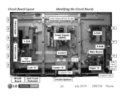
Circuit Board Layout FPC Y-Drive Upper FPC FPC Y-Drive Lower FPC FPC Y-SUS TCP Heat Sink Left "X" IR/LED Board Soft Touch Keyboard FPC Identifying the Circuit Boards Panel Voltage and Panel ID Label Power Supply (SMPS) Control AC In Center "X" Conductive Tape Invisible Speakers FPC Z-SUS Z-SUB Main Board Right "X" FPC FPC Side Input (part of main) Conductive Tape 20 July 2010 50PJ350 Plasma
Circuit Board Layout FPC Y-Drive Upper FPC FPC Y-Drive Lower FPC FPC Y-SUS TCP Heat Sink Left "X" IR/LED Board Soft Touch Keyboard FPC Identifying the Circuit Boards Panel Voltage and Panel ID Label Power Supply (SMPS) Control AC In Center "X" Conductive Tape Invisible Speakers FPC Z-SUS Z-SUB Main Board Right "X" FPC FPC Side Input (part of main) Conductive Tape 20 July 2010 50PJ350 Plasma
Training Manual
Page 21
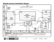
50PJ350 Connector Identification Diagram P101 Y-DRIVE UPPER Board PANEL p/n: EAJ60716304 (PDP50T10000.ADLGB) p/n: EAJ60716316 (PDP50T10000.ASLGB) P102 p/n: EBR63551601 P103 P201 P211 P210 P110 P204 Y-SUS Board p/n: EBR63039801 P205 P212 P101 P203 Y-DRIVE LOWER Board P812 SMPS POWER SUPPLY Board Top row Odd Back row Even p/n: EAY60968701 SC101 LN P813 P111 P102 n/c P121... RIGHT X Board p/n: EBR64062001 P101 FRONT IR Speakers (Front Right) p/n: EAB60962801 p/n: EBR65007704 Front "Soft Switch" Key Pad p/n: EAB60962801 Speakers (Front Left) 21 July 2010 50PJ350 Plasma
50PJ350 Connector Identification Diagram P101 Y-DRIVE UPPER Board PANEL p/n: EAJ60716304 (PDP50T10000.ADLGB) p/n: EAJ60716316 (PDP50T10000.ASLGB) P102 p/n: EBR63551601 P103 P201 P211 P210 P110 P204 Y-SUS Board p/n: EBR63039801 P205 P212 P101 P203 Y-DRIVE LOWER Board P812 SMPS POWER SUPPLY Board Top row Odd Back row Even p/n: EAY60968701 SC101 LN P813 P111 P102 n/c P121... RIGHT X Board p/n: EBR64062001 P101 FRONT IR Speakers (Front Right) p/n: EAB60962801 p/n: EBR65007704 Front "Soft Switch" Key Pad p/n: EAB60962801 Speakers (Front Left) 21 July 2010 50PJ350 Plasma
Training Manual
Page 22
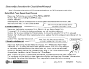
... 2010 50PJ350 Plasma Also, re-confirm VSC, -Vy and Z-Bias as well. Do not run the set with the Board Standoff Y-Drive Boards Removal connectors between the Y-SUS and Y-Drive Disconnect the following connectors: P812, P813 and SC101. Remove P204 or P110 by pulling the ribbon cable upward. Switch Mode Power Supply Board...
... 2010 50PJ350 Plasma Also, re-confirm VSC, -Vy and Z-Bias as well. Do not run the set with the Board Standoff Y-Drive Boards Removal connectors between the Y-SUS and Y-Drive Disconnect the following connectors: P812, P813 and SC101. Remove P204 or P110 by pulling the ribbon cable upward. Switch Mode Power Supply Board...
Training Manual
Page 29
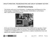
CIRCUIT OPERATION, TROUBLESHOOTING AND CIRCUIT ALIGNMENT SECTION 50PJ350 Plasma Display This Section will cover Circuit Operation, Troubleshooting and Alignment of this Section the technician should be able with confidence to adjust the controls. The technician should understand the operation of each circuit board and how to troubleshoot a circuit board failure, replace the defective circuit and perform all necessary adjustments. 29 July 2010 50PJ350 Plasma At the end of the Power Supply, Y-SUS Board, Y-Drive Boards, Z-SUS Board, Control Board, Main Board and the X Drive Boards.
CIRCUIT OPERATION, TROUBLESHOOTING AND CIRCUIT ALIGNMENT SECTION 50PJ350 Plasma Display This Section will cover Circuit Operation, Troubleshooting and Alignment of this Section the technician should be able with confidence to adjust the controls. The technician should understand the operation of each circuit board and how to troubleshoot a circuit board failure, replace the defective circuit and perform all necessary adjustments. 29 July 2010 50PJ350 Plasma At the end of the Power Supply, Y-SUS Board, Y-Drive Boards, Z-SUS Board, Control Board, Main Board and the X Drive Boards.
Training Manual
Page 32
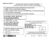
... with new panel 3) A Picture issue is encountered 4) As a general rule of thumb when ever the back is removed ADJUSTMENT ORDER "IMPORTANT" DC VOLTAGE ADJUSTMENTS 1) POWER SUPPLY: VS, VA (Always do first) 2) Y-SUS: Adjust -Vy, VSC 3) Z-SUS: Adjust Z-Bias (VZB) WAVEFORM ADJUSTMENTS 1) Y-SUS: Set-Up, Set-...Set-Up -Vy Vsc Ve ZBias Panel "Rear View" All label references are not the same for every panel encountered. 32 July 2010 50PJ350 Plasma Power Supply The Waveform adjustment is only necessary 1) When the Y-SUS board is replaced 2) When a "Mal-Discharge" problem is encountered 3) When an...
... with new panel 3) A Picture issue is encountered 4) As a general rule of thumb when ever the back is removed ADJUSTMENT ORDER "IMPORTANT" DC VOLTAGE ADJUSTMENTS 1) POWER SUPPLY: VS, VA (Always do first) 2) Y-SUS: Adjust -Vy, VSC 3) Z-SUS: Adjust Z-Bias (VZB) WAVEFORM ADJUSTMENTS 1) Y-SUS: Set-Up, Set-...Set-Up -Vy Vsc Ve ZBias Panel "Rear View" All label references are not the same for every panel encountered. 32 July 2010 50PJ350 Plasma Power Supply The Waveform adjustment is only necessary 1) When the Y-SUS board is replaced 2) When a "Mal-Discharge" problem is encountered 3) When an...
Training Manual
Page 33
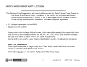
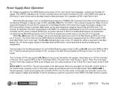
SMPS p/n: EAY60968701 Check the silk screen label on the top center of the Power Supply board to Panel even in this Power Supply. 33 July 2010 50PJ350 Plasma Set-Up and Ve are just for Label location identification and are not adjusted in the same size category. On... of the section the technician will have a better understanding of the operation of the Power Supply Circuit and will cover troubleshooting the Switch Mode Power Supply for the Single Scan Plasma. SWITCH MODE POWER SUPPLY SECTION This Section of the Presentation will be able to locate voltage and test points needed...
SMPS p/n: EAY60968701 Check the silk screen label on the top center of the Power Supply board to Panel even in this Power Supply. 33 July 2010 50PJ350 Plasma Set-Up and Ve are just for Label location identification and are not adjusted in the same size category. On... of the section the technician will have a better understanding of the operation of the Power Supply Circuit and will cover troubleshooting the Switch Mode Power Supply for the Single Scan Plasma. SWITCH MODE POWER SUPPLY SECTION This Section of the Presentation will be able to locate voltage and test points needed...
Training Manual
Page 34
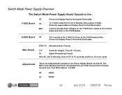
... Z-SUS). All adjustments are 2 adjustments located on the Y-SUS then routed to the Control board and then to the Z-SUS Board. Switch Mode Power Supply Overview The Switch Mode Power Supply Board Outputs to Chassis Ground. To Y-SUS, fused then to the X-Boards. (Not used ) Adjustments There are made referenced to the : VS Y-SUS...the Z-SUS board which Drives the Display Panel's Horizontal Electrodes. The M5V is routed to the Y-SUS first then to develop Bias Voltages on the Power Supply Board VA and VS. Use "Full White Raster" 100 IRE VS VR901 VA VR502 34 July 2010...
... Z-SUS). All adjustments are 2 adjustments located on the Y-SUS then routed to the Control board and then to the Z-SUS Board. Switch Mode Power Supply Overview The Switch Mode Power Supply Board Outputs to Chassis Ground. To Y-SUS, fused then to the X-Boards. (Not used ) Adjustments There are made referenced to the : VS Y-SUS...the Z-SUS board which Drives the Display Panel's Horizontal Electrodes. The M5V is routed to the Y-SUS first then to develop Bias Voltages on the Power Supply Board VA and VS. Use "Full White Raster" 100 IRE VS VR901 VA VR502 34 July 2010...
Training Manual
Page 35
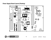
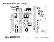
Power Supply Board Layout (Drawing) P812 VA TP VS TP F801 4A 250V Stand-By: 0.9V Run: 388V VS and VA TP ZD803 D805 T901 SMPS p/n: EAY60968701 T902 VR901 VS Adj VR502 VA Adj ZD302 D609 ZD401 D601 D307 ZD301 ZD303 D601 D303 ZD101 D305 Stand-By: 1.5V Run: 388V L601 D308 D309 D306 D302 F302 2.5A 250V T301 D103 D301 L602 F101 10A 250V SC101 P813 35 July 2010 50PJ350 Plasma
Power Supply Board Layout (Drawing) P812 VA TP VS TP F801 4A 250V Stand-By: 0.9V Run: 388V VS and VA TP ZD803 D805 T901 SMPS p/n: EAY60968701 T902 VR901 VS Adj VR502 VA Adj ZD302 D609 ZD401 D601 D307 ZD301 ZD303 D601 D303 ZD101 D305 Stand-By: 1.5V Run: 388V L601 D308 D309 D306 D302 F302 2.5A 250V T301 D103 D301 L602 F101 10A 250V SC101 P813 35 July 2010 50PJ350 Plasma
Training Manual
Page 36
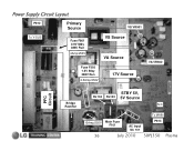
Power Supply Circuit Layout P812 Primary Source VS VR901 To Y-SUS Fuse F801 0.9V Stby 388V Run 4Amp/250V VS Source VA Source Fuse F302 1.5V Stby 388V Run 2.5Amp/250V 17V Source VA VR502 PFC Circuit Bridge Rectifier STBY 5V, RL104 RL103 5V Source N/C To MAIN 10Amp/250V 36 Main Fuse F101 AC Input SC 101 P813 July 2010 50PJ350 Plasma
Power Supply Circuit Layout P812 Primary Source VS VR901 To Y-SUS Fuse F801 0.9V Stby 388V Run 4Amp/250V VS Source VA Source Fuse F302 1.5V Stby 388V Run 2.5Amp/250V 17V Source VA VR502 PFC Circuit Bridge Rectifier STBY 5V, RL104 RL103 5V Source N/C To MAIN 10Amp/250V 36 Main Fuse F101 AC Input SC 101 P813 July 2010 50PJ350 Plasma
Training Manual
Page 37
... is sensed and monitored by the Main Microprocessor (IC1). AC Detection (AC Det) is generated on the SMPS, by the Controller IC701, turning on the power supply in this state, the Controller turns on the M5V line and outputs at P813 pins 1 and 2 and used . When RL_ON arrives, the run voltage +5V... pins 4 and 5 to the Z-SUS P2. AUTO GND Pin 18 of the SMPS if the Main board is suspect. 37 July 2010 50PJ350 Plasma When the Microprocessor (IC1) on the power supply via P813 (5.17V at Pin 15 of the A/C Line and routed to the Controller (IC701) where it outputs a high (2.43V) called...
... is sensed and monitored by the Main Microprocessor (IC1). AC Detection (AC Det) is generated on the SMPS, by the Controller IC701, turning on the power supply in this state, the Controller turns on the M5V line and outputs at P813 pins 1 and 2 and used . When RL_ON arrives, the run voltage +5V... pins 4 and 5 to the Z-SUS P2. AUTO GND Pin 18 of the SMPS if the Main board is suspect. 37 July 2010 50PJ350 Plasma When the Microprocessor (IC1) on the power supply via P813 (5.17V at Pin 15 of the A/C Line and routed to the Controller (IC701) where it outputs a high (2.43V) called...
Training Manual
Page 38
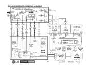
... 3.3V Reg IC302 3.3VST 5 17V Audio IC801 +5V HDMI EDID And other circuits 2 Reset C108, D1, 3 R62 6 Error Relay Det. It is 388V F801 POWER SUPPLY 7 AC In Stand-By 0.9V Run 388V (SMPS) 1 Stand AC By 5V Reg Det STBY RUN +5V 9 Regulator 5 17V 3.46V 5.14V Reg 8 M5V ...X PWB 8 Center Va 3.3V 7 8 Va 7 X PWB Right 2 Front IR 4 Board Soft Touch Key Pad Remote Power Key Power Key 38 July 2010 50PJ350 Plasma Det. 5V 5V 17V 6 2 If missing set will not turn on. 50PJ350 POWER SUPPLY START UP SEQUENCE F302 In Stand-By Primary side is 1.5V In Run (Relay On) Primary side...
... 3.3V Reg IC302 3.3VST 5 17V Audio IC801 +5V HDMI EDID And other circuits 2 Reset C108, D1, 3 R62 6 Error Relay Det. It is 388V F801 POWER SUPPLY 7 AC In Stand-By 0.9V Run 388V (SMPS) 1 Stand AC By 5V Reg Det STBY RUN +5V 9 Regulator 5 17V 3.46V 5.14V Reg 8 M5V ...X PWB 8 Center Va 3.3V 7 8 Va 7 X PWB Right 2 Front IR 4 Board Soft Touch Key Pad Remote Power Key Power Key 38 July 2010 50PJ350 Plasma Det. 5V 5V 17V 6 2 If missing set will not turn on. 50PJ350 POWER SUPPLY START UP SEQUENCE F302 In Stand-By Primary side is 1.5V In Run (Relay On) Primary side...
Training Manual
Page 39
Power Supply Board Layout (Drawing) P812 VA TP VS TP F801 4A 250V Stand-By: 0.9V Run: 388V VS and VA TP ZD803 D805 T901 SMPS p/n: EAY60968701 T902 VR901 VS Adj VR502 VA Adj ZD302 D609 ZD401 D601 D307 ZD301 ZD303 D601 D303 ZD101 D305 Stand-By: 1.5V Run: 388V L601 D308 D309 D306 D302 F302 2.5A 250V T301 D103 D301 L602 F101 10A 250V SC101 P813 39 July 2010 50PJ350 Plasma
Power Supply Board Layout (Drawing) P812 VA TP VS TP F801 4A 250V Stand-By: 0.9V Run: 388V VS and VA TP ZD803 D805 T901 SMPS p/n: EAY60968701 T902 VR901 VS Adj VR502 VA Adj ZD302 D609 ZD401 D601 D307 ZD301 ZD303 D601 D303 ZD101 D305 Stand-By: 1.5V Run: 388V L601 D308 D309 D306 D302 F302 2.5A 250V T301 D103 D301 L602 F101 10A 250V SC101 P813 39 July 2010 50PJ350 Plasma
Training Manual
Page 40
...successful and all other end to SC101. AC DET WILL NOT be fairly assured the power supply is missing, the TV will come on . L602 Note: To turn on the Power Supply; 1) With Main Board connected, press power. 2) Without Main Board connected SMPS will turn on and VS is applied to ...8 P812 VA VS Test Points F801 4A 250V T901 T902 POWER SUPPLY p/n: EAY60968701 ZD302 D609 ZD401 VR901 VS Adj VR502 VA Adj P812 Check Pins 1 or 2 for Vs voltage Check Pins 6 or 7 for AC Det (4.44V) 40 July 2010 50PJ350 Plasma Abnormal operational conditions may result if not loaded. If AC...
...successful and all other end to SC101. AC DET WILL NOT be fairly assured the power supply is missing, the TV will come on . L602 Note: To turn on the Power Supply; 1) With Main Board connected, press power. 2) Without Main Board connected SMPS will turn on and VS is applied to ...8 P812 VA VS Test Points F801 4A 250V T901 T902 POWER SUPPLY p/n: EAY60968701 ZD302 D609 ZD401 VR901 VS Adj VR502 VA Adj P812 Check Pins 1 or 2 for Vs voltage Check Pins 6 or 7 for AC Det (4.44V) 40 July 2010 50PJ350 Plasma Abnormal operational conditions may result if not loaded. If AC...
Training Manual
Page 41
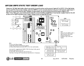
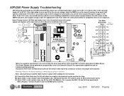
.... P812 (VS pins 1 and 2) (VA pins 6 and 7) and (M5V pins 9 and 10). 100Ω 100Ω 41 July 2010 50PJ350 Plasma 50PJ350 Power Supply Troubleshooting With P813 disconnected from the Main board (P301) attach two 100 Watt light bulbs, attach one section at a time. (B) Add a 100Ω...; ¼ watt resistor from Vs to Ground will assure the power supply will regulate with a load and no other end to ground. ...
.... P812 (VS pins 1 and 2) (VA pins 6 and 7) and (M5V pins 9 and 10). 100Ω 100Ω 41 July 2010 50PJ350 Plasma 50PJ350 Power Supply Troubleshooting With P813 disconnected from the Main board (P301) attach two 100 Watt light bulbs, attach one section at a time. (B) Add a 100Ω...; ¼ watt resistor from Vs to Ground will assure the power supply will regulate with a load and no other end to ground. ...
Training Manual
Page 43
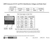
... SC101 and P812 Identification, Voltages and Diode Check SC101 AC INPUT Connector SC101 Pin Number L and N Standby 120VAC Run 120VAC Diode Mode Open P812 P812 "Power Supply" to Y-SUS "P210" Va TP 1 Vs TP Pin 1, 2 3 4, 5 6, 7 8 9, 10 Label *Vs n/c Gnd *Va Gnd M5V Run *206V n/c Gnd *60V Gnd 5V Diode... Mode Open n/c Gnd Open Gnd 2.16V * Note: This voltage will vary in Diode Mode. 43 July 2010 50PJ350 Plasma Vs routed to Z-SUS. M5V routed through Y-SUS to Control board and then to Z-SUS from P211. DVM in accordance with all connectors Disconnected...
... SC101 and P812 Identification, Voltages and Diode Check SC101 AC INPUT Connector SC101 Pin Number L and N Standby 120VAC Run 120VAC Diode Mode Open P812 P812 "Power Supply" to Y-SUS "P210" Va TP 1 Vs TP Pin 1, 2 3 4, 5 6, 7 8 9, 10 Label *Vs n/c Gnd *Va Gnd M5V Run *206V n/c Gnd *60V Gnd 5V Diode... Mode Open n/c Gnd Open Gnd 2.16V * Note: This voltage will vary in Diode Mode. 43 July 2010 50PJ350 Plasma Vs routed to Z-SUS. M5V routed through Y-SUS to Control board and then to Z-SUS from P211. DVM in accordance with all connectors Disconnected...
Training Manual
Page 45
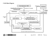
... FG5V Logic signals needed to scan the panel Y-Drive Boards Receive Scan Waveform Display Panel Logic signals needed to generate drive waveform 45 July 2010 50PJ350 Plasma Y-SUS Block Diagram Power Supply Board -
... FG5V Logic signals needed to scan the panel Y-Drive Boards Receive Scan Waveform Display Panel Logic signals needed to generate drive waveform 45 July 2010 50PJ350 Plasma Y-SUS Block Diagram Power Supply Board -


