
Owner's Manual
Page 3
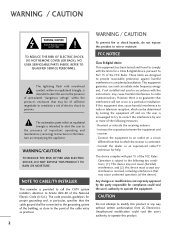
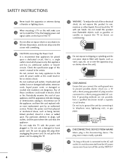
...modifications not expressly approved by one or more of the following two conditions: (1) This device may cause harmful interference to comply with part 15 of electric shock to modify this product in a particular installation. REFER TO QUALIFIED SERVICE PERSONNEL. FCC NOTICE Class B digital ...not attempt to persons. This equipment generates, uses and can be determined by turning the equipment off and on a circuit different from LG Electronics. Reorient or relocate the receiving antenna. - NOTE TO CABLE/TV INSTALLER This reminder is subject to rain or moisture. If ...
...modifications not expressly approved by one or more of the following two conditions: (1) This device may cause harmful interference to comply with part 15 of electric shock to modify this product in a particular installation. REFER TO QUALIFIED SERVICE PERSONNEL. FCC NOTICE Class B digital ...not attempt to persons. This equipment generates, uses and can be determined by turning the equipment off and on a circuit different from LG Electronics. Reorient or relocate the receiving antenna. - NOTE TO CABLE/TV INSTALLER This reminder is subject to rain or moisture. If ...
Owner's Manual
Page 5
... attention to unplug the TV. 15 WARNING - Periodically examine the cord of fire or electrical shock, do not place objects filled with an exact replacement part by an authorized servicer. When mounting a TV on or over the apparatus (e.g. SAFETY INSTRUCTIONS 11 Never touch this unit by SWITCH" 4
... attention to unplug the TV. 15 WARNING - Periodically examine the cord of fire or electrical shock, do not place objects filled with an exact replacement part by an authorized servicer. When mounting a TV on or over the apparatus (e.g. SAFETY INSTRUCTIONS 11 Never touch this unit by SWITCH" 4
Owner's Manual
Page 16
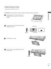
x 3 M5x14 Stand Body Stand Base 3 Assemble the TV as shown. 4 Fix the 4 bolts securely using the holes in the back of the TV. x 4 M4x28 15 Installation (Except 60PK250, 60PK540, 60PK550, 60PK280, 60PK290, 60PK550C) 1 Carefully place the TV screen side down on a cushioned surface to protect the screen from your TV. PREPARATION STAND INSTRUCTION I Image shown may differ from damage. 2 Assemble the parts of the Stand Body with the Stand Base of the TV.
x 3 M5x14 Stand Body Stand Base 3 Assemble the TV as shown. 4 Fix the 4 bolts securely using the holes in the back of the TV. x 4 M4x28 15 Installation (Except 60PK250, 60PK540, 60PK550, 60PK280, 60PK290, 60PK550C) 1 Carefully place the TV screen side down on a cushioned surface to protect the screen from your TV. PREPARATION STAND INSTRUCTION I Image shown may differ from damage. 2 Assemble the parts of the Stand Body with the Stand Base of the TV.
Owner's Manual
Page 20
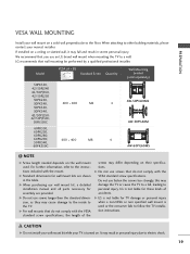
...damage or personal injury when a non-VESA or non specified wall mount is used . G LG is not liable for wall mount kits are provided. If installed on a ceiling or slanted.... G When purchasing our wall mount kit, a detailed installation manual and all parts necessary for these kinds of the screws may differ depending on their specifications. G...nearest installer. Model VESA (A * B) A Standard Screw Quantity B Wall Mounting bracket (sold separately) 50PK550, 42/50PJ340 42/50PJ350, 42/50PJ250 50PK250, 50PK340, 400 * 400 M6 50PK350, 50PK540, 42/50PJ550, 42/50PJ350C, 50PK550C...
...damage or personal injury when a non-VESA or non specified wall mount is used . G LG is not liable for wall mount kits are provided. If installed on a ceiling or slanted.... G When purchasing our wall mount kit, a detailed installation manual and all parts necessary for these kinds of the screws may differ depending on their specifications. G...nearest installer. Model VESA (A * B) A Standard Screw Quantity B Wall Mounting bracket (sold separately) 50PK550, 42/50PJ340 42/50PJ350, 42/50PJ250 50PK250, 50PK340, 400 * 400 M6 50PK350, 50PK540, 42/50PJ550, 42/50PJ350C, 50PK550C...
Owner's Manual
Page 71
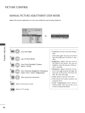
.... E PICTURE CONTROL PICTURE CONTROL MANUAL PICTURE ADJUSTMENT-USER MODE Adjust the picture appearance to make picture bluish. 70 You may use Contrast when the bright part of the picture is saturated. You may use brightness when the dark...
.... E PICTURE CONTROL PICTURE CONTROL MANUAL PICTURE ADJUSTMENT-USER MODE Adjust the picture appearance to make picture bluish. 70 You may use Contrast when the bright part of the picture is saturated. You may use brightness when the dark...
Owner's Manual
Page 74
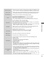
.../Mgt/Yellow). This feature enhances hue, saturation and luminance so that they look more vivid. a. Color difference may not be used by making bright parts brighter and dark parts darker. The picture is -30 +30. - Otherwise, 'Black level' is -50 - +50. Low : Make dark and middle gray level area of a different video...
.../Mgt/Yellow). This feature enhances hue, saturation and luminance so that they look more vivid. a. Color difference may not be used by making bright parts brighter and dark parts darker. The picture is -30 +30. - Otherwise, 'Black level' is -50 - +50. Low : Make dark and middle gray level area of a different video...

Owner's Manual
Page 120
...] [Data02][Data03][Data04][x][a][ ][Set ID] [ ][NG][Data00][x] 119 Tune to change the channel. * 6th bit: Use a two part or one part channel. Acknowledgement [c][ ][Set ID][ ][OK/NG][Data][x] * Tune Command Examples: 1. Data 00 = Don't know Physical = 00... = 0000 0001 in Hex. * 7th bit : For which must be converted to the digital (ATSC) local channel 30-3. Data 05: 7 Main/Sub Picture 6 Two/One Part Channel 5 Using Physical 4 Channel Reserved 3 2 1 0 Step 0 Main 1 Sub 0 Two 1 One 0 Use x 0 0 0 0 NTSC Air 1 No Use x 0 0 0 1 NTSC Cable x 0 0 1 0 ATSC Air x...
...] [Data02][Data03][Data04][x][a][ ][Set ID] [ ][NG][Data00][x] 119 Tune to change the channel. * 6th bit: Use a two part or one part channel. Acknowledgement [c][ ][Set ID][ ][OK/NG][Data][x] * Tune Command Examples: 1. Data 00 = Don't know Physical = 00... = 0000 0001 in Hex. * 7th bit : For which must be converted to the digital (ATSC) local channel 30-3. Data 05: 7 Main/Sub Picture 6 Two/One Part Channel 5 Using Physical 4 Channel Reserved 3 2 1 0 Step 0 Main 1 Sub 0 Two 1 One 0 Use x 0 0 0 0 NTSC Air 1 No Use x 0 0 0 1 NTSC Cable x 0 0 1 0 ATSC Air x...
Training Manual
Page 4
...) (800) 243-0000 Technical Support (and Part Sales) (800) 847-7597 USA Website (GSFS) http://gsfs-america.lge.com Customer Service Website us.lgservice.com Knowledgebase Website LG Web Training LG CS Academy lgtechassist.com lge.webex.com lgcsacademy.com New: Software Downloads Technical Assistance Presentations with ...Bookmarks Plasma Control Board ROM Update (Jig required) New Training Materials on the Learning Academy site Published July 2010 by LG Technical Support and Training LG Electronics Alabama, Inc. 201 James Record Road, Huntsville, AL, 35813. 4 July 2010 50PJ350 Plasma
...) (800) 243-0000 Technical Support (and Part Sales) (800) 847-7597 USA Website (GSFS) http://gsfs-america.lge.com Customer Service Website us.lgservice.com Knowledgebase Website LG Web Training LG CS Academy lgtechassist.com lge.webex.com lgcsacademy.com New: Software Downloads Technical Assistance Presentations with ...Bookmarks Plasma Control Board ROM Update (Jig required) New Training Materials on the Learning Academy site Published July 2010 by LG Technical Support and Training LG Electronics Alabama, Inc. 201 James Record Road, Huntsville, AL, 35813. 4 July 2010 50PJ350 Plasma
Training Manual
Page 6
... sensitive. This equipment generates, uses, and can weaken or damage the electronics in a residential installation. Before removing a replacement part from its edges only. However, there is no guarantee that interference will not occur in an anti-static bag, observe these... same precautions. When repackaging a failed electronic control assembly in a particular installation. Connect an ESD wrist strap to Part 15 of the following measures: Reorient or relocate the receiving antenna; ESD Notice (Electrostatic Static Discharge) Today's sophisticated electronics ...
... sensitive. This equipment generates, uses, and can weaken or damage the electronics in a residential installation. Before removing a replacement part from its edges only. However, there is no guarantee that interference will not occur in an anti-static bag, observe these... same precautions. When repackaging a failed electronic control assembly in a particular installation. Connect an ESD wrist strap to Part 15 of the following measures: Reorient or relocate the receiving antenna; ESD Notice (Electrostatic Static Discharge) Today's sophisticated electronics ...
Training Manual
Page 7
...; volt) unless otherwise specified. 4. Check the model label. Be cautious of residual current stored before any adjustments are used extensively for both physical damage and part number accuracy. 2. The PDP Module must be transported vertically NOT horizontally. 7. The Plasma television should be Considered 1. New Panels and Frames are completely discharged because...
...; volt) unless otherwise specified. 4. Check the model label. Be cautious of residual current stored before any adjustments are used extensively for both physical damage and part number accuracy. 2. The PDP Module must be transported vertically NOT horizontally. 7. The Plasma television should be Considered 1. New Panels and Frames are completely discharged because...

Training Manual
Page 8
... after giving a thorough examination using your senses Sight, Smell, Touch and Hearing. Look for correct Amplitude Phasing and Timing of the signals. Look for burned parts and check for the proper Duty Cycle of the signals also check for possible overheated components. Always confirm the supplies are not only the proper...
... after giving a thorough examination using your senses Sight, Smell, Touch and Hearing. Look for correct Amplitude Phasing and Timing of the signals. Look for burned parts and check for the proper Duty Cycle of the signals also check for possible overheated components. Always confirm the supplies are not only the proper...
Training Manual
Page 20
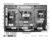
Circuit Board Layout FPC Y-Drive Upper FPC FPC Y-Drive Lower FPC FPC Y-SUS TCP Heat Sink Left "X" IR/LED Board Soft Touch Keyboard FPC Identifying the Circuit Boards Panel Voltage and Panel ID Label Power Supply (SMPS) Control AC In Center "X" Conductive Tape Invisible Speakers FPC Z-SUS Z-SUB Main Board Right "X" FPC FPC Side Input (part of main) Conductive Tape 20 July 2010 50PJ350 Plasma
Circuit Board Layout FPC Y-Drive Upper FPC FPC Y-Drive Lower FPC FPC Y-SUS TCP Heat Sink Left "X" IR/LED Board Soft Touch Keyboard FPC Identifying the Circuit Boards Panel Voltage and Panel ID Label Power Supply (SMPS) Control AC In Center "X" Conductive Tape Invisible Speakers FPC Z-SUS Z-SUB Main Board Right "X" FPC FPC Side Input (part of main) Conductive Tape 20 July 2010 50PJ350 Plasma
Training Manual
Page 33
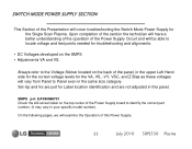
... the Power Supply board to Panel even in the same size category. On the following pages, we will vary from Panel to identify the correct part number. (It may vary in the upper Left Hand side for the correct voltage levels for troubleshooting and alignments. • DC Voltages developed on the...
... the Power Supply board to Panel even in the same size category. On the following pages, we will vary from Panel to identify the correct part number. (It may vary in the upper Left Hand side for the correct voltage levels for troubleshooting and alignments. • DC Voltages developed on the...


