Setup Guide
Page 5
... Inspiron Laptop 5 Before Setting Up Your Computer 5 Connect the AC Adapter 6 Connect the Network Cable (Optional 7 Press the Power Button 8 Set Up the Operating System 9 Create System Recovery Media (Recommended 10 Enable or Disable Wireless (Optional 12 Set Up Wireless Display (Optional 14 Connect to the Internet (Optional 16 Using Your Inspiron Laptop 18 Right View Features 18 Left View Features 20 Back View Features 24 Front View Features 26 Status Lights and Indicators 28 Disabling Battery Charging 29 Computer Base and Keyboard Features 30 Touch Pad...
... Inspiron Laptop 5 Before Setting Up Your Computer 5 Connect the AC Adapter 6 Connect the Network Cable (Optional 7 Press the Power Button 8 Set Up the Operating System 9 Create System Recovery Media (Recommended 10 Enable or Disable Wireless (Optional 12 Set Up Wireless Display (Optional 14 Connect to the Internet (Optional 16 Using Your Inspiron Laptop 18 Right View Features 18 Left View Features 20 Back View Features 24 Front View Features 26 Status Lights and Indicators 28 Disabling Battery Charging 29 Computer Base and Keyboard Features 30 Touch Pad...
Setup Guide
Page 6
... Beep Codes 54 Touch Screen Problems 55 Network Problems 56 Power Problems 56 Memory Problems 58 Lockups and Software Problems 58 Using Support Tools 61 Dell Support Center 61 My Dell Downloads 62 Hardware Troubleshooter 63 Dell Diagnostics 63 Restoring Your Operating System 65 System Restore 66 Dell DataSafe Local Backup 67 System Recovery Media 70 Dell Factory Image Restore 71 Getting Help 73 Technical Support and Customer Service 74 DellConnect 74 Online Services 75 Automated Order-Status Service 76 Product Information 76 Returning Items for Repair...
... Beep Codes 54 Touch Screen Problems 55 Network Problems 56 Power Problems 56 Memory Problems 58 Lockups and Software Problems 58 Using Support Tools 61 Dell Support Center 61 My Dell Downloads 62 Hardware Troubleshooter 63 Dell Diagnostics 63 Restoring Your Operating System 65 System Restore 66 Dell DataSafe Local Backup 67 System Recovery Media 70 Dell Factory Image Restore 71 Getting Help 73 Technical Support and Customer Service 74 DellConnect 74 Online Services 75 Automated Order-Status Service 76 Product Information 76 Returning Items for Repair...
Setup Guide
Page 12
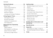
... the hardware, software, drivers, or other system settings have left the computer in when you set up Microsoft Windows. The system recovery media can use the system recovery media if changes to create the system recovery media: • Dell DataSafe Local Backup • USB key with a minimum capacity of the Operating System disc). You can be used to restore your computer to the operating state it was in an undesirable operating state. Setting Up Your Inspiron Laptop Create System Recovery Media...
... the hardware, software, drivers, or other system settings have left the computer in when you set up Microsoft Windows. The system recovery media can use the system recovery media if changes to create the system recovery media: • Dell DataSafe Local Backup • USB key with a minimum capacity of the Operating System disc). You can be used to restore your computer to the operating state it was in an undesirable operating state. Setting Up Your Inspiron Laptop Create System Recovery Media...
Setup Guide
Page 17
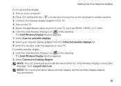
... wireless display adapter documentation. 15 Select your TV, such as HDMI1, HDMI2, or S-Video. 6. Click the Intel Wireless Display icon on the keyboard to enable wireless. 3. NOTE: You can download and install the latest driver for your wireless display adapter from support.dell.com. Press along with the < > on the function key row on the desktop. The Intel Wireless Display window appears. 2. Select Scan for available displays. 8. To enable wireless display: 1. Connect the wireless display adapter to Existing Adapter. Setting Up Your Inspiron Laptop...
... wireless display adapter documentation. 15 Select your TV, such as HDMI1, HDMI2, or S-Video. 6. Click the Intel Wireless Display icon on the keyboard to enable wireless. 3. NOTE: You can download and install the latest driver for your wireless display adapter from support.dell.com. Press along with the < > on the function key row on the desktop. The Intel Wireless Display window appears. 2. Select Scan for available displays. 8. To enable wireless display: 1. Connect the wireless display adapter to Existing Adapter. Setting Up Your Inspiron Laptop...
Setup Guide
Page 18
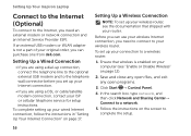
... setup. 16 Setting Up a Wireless Connection NOTE: To set up your computer (see the documentation that wireless is not a part of your original order, you can use your wireless Internet connection, you need an external modem or network connection and an Internet Service Provider (ISP). Save and close any open files, and exit any open programs. 3. Click Start → Control Panel. 4. Follow the instructions on page 12). 2. Setting Up Your Inspiron Laptop Connect to the Internet (Optional) To connect to a network. 5. To set...
... setup. 16 Setting Up a Wireless Connection NOTE: To set up your computer (see the documentation that wireless is not a part of your original order, you can use your wireless Internet connection, you need an external modem or network connection and an Internet Service Provider (ISP). Save and close any open files, and exit any open programs. 3. Click Start → Control Panel. 4. Follow the instructions on page 12). 2. Setting Up Your Inspiron Laptop Connect to the Internet (Optional) To connect to a network. 5. To set...
Setup Guide
Page 33
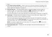
... display enable or disable key , wireless enable or disable key , touch pad enable or disable key , brightness increase and decrease keys, and the multimedia keys are located in the notification area of a mouse to turn on page 38. 3 Touch pad - NOTE: To enable or disable the touch pad, press along with the < > key on the function key row on page 36. For more information, see "Touch Pad Gestures" on the keyboard. 4 Touch pad buttons (2) - Provide left -click by tapping the surface. Using Your Inspiron Laptop 1 Power button and light - The light...
... display enable or disable key , wireless enable or disable key , touch pad enable or disable key , brightness increase and decrease keys, and the multimedia keys are located in the notification area of a mouse to turn on page 38. 3 Touch pad - NOTE: To enable or disable the touch pad, press along with the < > key on the function key row on page 36. For more information, see "Touch Pad Gestures" on the keyboard. 4 Touch pad buttons (2) - Provide left -click by tapping the surface. Using Your Inspiron Laptop 1 Power button and light - The light...
Setup Guide
Page 56
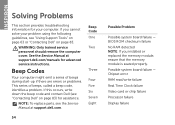
... Video card or chip failure Processor failure Display failure Beep Code One Two Three Four Five Six Seven Eight 54 Possible Problem Possible system board failure - WARNING: Only trained service personnel should remove the computer cover. NOTE: To replace parts, see "Using Support Tools" on page 63 or "Contacting Dell" on page 83) for your problem using the following guidelines, see the Service Manual at support.dell.com/manuals for advanced service instructions. INSPIRON...
... Video card or chip failure Processor failure Display failure Beep Code One Two Three Four Five Six Seven Eight 54 Possible Problem Possible system board failure - WARNING: Only trained service personnel should remove the computer cover. NOTE: To replace parts, see "Using Support Tools" on page 63 or "Contacting Dell" on page 83) for your problem using the following guidelines, see the Service Manual at support.dell.com/manuals for advanced service instructions. INSPIRON...
Setup Guide
Page 59
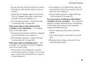
... the problem persists, contact Dell (see "Contacting Dell" on the touch pad, or press the power button to the same electrical outlet. 57 If the power light is solid white and the computer is breathing white - If the power light is not responding - The computer is in standby mode or the display may not be responding. • Press a key on the keyboard, move the connected mouse or...
... the problem persists, contact Dell (see "Contacting Dell" on the touch pad, or press the power button to the same electrical outlet. 57 If the power light is solid white and the computer is breathing white - If the power light is not responding - The computer is in standby mode or the display may not be responding. • Press a key on the keyboard, move the connected mouse or...
Setup Guide
Page 60
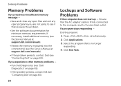
... resolves the problem. • See the software documentation for minimum memory requirements. Click End Task. 58 Press simultaneously. 2. If a program stops responding - End the program: 1. If necessary, install additional memory (see the Service Manual at support.dell.com/manuals). • Reseat the memory module(s) into the connector(s) (see the Service Manual at support.dell.com/manuals). • If the problem persists, contact Dell (see if that is firmly connected to...
... resolves the problem. • See the software documentation for minimum memory requirements. Click End Task. 58 Press simultaneously. 2. If a program stops responding - End the program: 1. If necessary, install additional memory (see the Service Manual at support.dell.com/manuals). • Reseat the memory module(s) into the connector(s) (see the Service Manual at support.dell.com/manuals). • If the problem persists, contact Dell (see if that is firmly connected to...
Setup Guide
Page 86
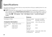
... Information section in the Dell Support Center. NOTE: Offerings may need when setting up, updating drivers for, and upgrading your computer. INSPIRON Specifications This section provides information that you may vary by region. Computer Model Memory Dell Inspiron N7110 Computer Information System chipset Mobile Intel 6 series Processor types Intel Core i3 Intel Core i5 Intel Core i7 Memory module connector Memory module capacities Minimum memory Maximum memory two user-accessible SODIMM connectors 1 GB, 2 GB...
... Information section in the Dell Support Center. NOTE: Offerings may need when setting up, updating drivers for, and upgrading your computer. INSPIRON Specifications This section provides information that you may vary by region. Computer Model Memory Dell Inspiron N7110 Computer Information System chipset Mobile Intel 6 series Processor types Intel Core i3 Intel Core i5 Intel Core i7 Memory module connector Memory module capacities Minimum memory Maximum memory two user-accessible SODIMM connectors 1 GB, 2 GB...
Setup Guide
Page 96
Index power problems, solving 56 power strips, using 6 problems, solving 54 products information and purchasing 76 R resources, finding more 82 restoring factory image 71 S Service Tag locating 79 setup, before you begin 5 shipping products for return or repair 77 software features 50 software problems 58 solving problems 54 94 specifications 84 support e-mail addresses 75 support sites worldwide 74 System Recovery Media 70 system reinstall options 65 System Restore 66 T Touch Pad Gestures 34 Touch screen Gestures 42 U Using the Emergency Eject Hole 38 V ventilation, ensuring 5
Index power problems, solving 56 power strips, using 6 problems, solving 54 products information and purchasing 76 R resources, finding more 82 restoring factory image 71 S Service Tag locating 79 setup, before you begin 5 shipping products for return or repair 77 software features 50 software problems 58 solving problems 54 94 specifications 84 support e-mail addresses 75 support sites worldwide 74 System Recovery Media 70 system reinstall options 65 System Restore 66 T Touch Pad Gestures 34 Touch screen Gestures 42 U Using the Emergency Eject Hole 38 V ventilation, ensuring 5
Service Manual
Page 4
Replacing the Module Cover 22 6 Memory Module(s 23 Removing the Memory Module(s 23 Replacing the Memory Module(s 24 7 Keyboard 27 Removing the Keyboard 27 Replacing the Keyboard 29 8 Palm-Rest Assembly 31 Removing the Palm-Rest Assembly 31 Replacing the Palm-Rest Assembly 35 9 Hot-Key Board 37 Removing the Hot-Key Board 37 Replacing the Hot-Key Board 38 10 Power-Button Board 41 Removing the Power-Button Board 41 Replacing the Power-Button Board 42 4 Contents
Replacing the Module Cover 22 6 Memory Module(s 23 Removing the Memory Module(s 23 Replacing the Memory Module(s 24 7 Keyboard 27 Removing the Keyboard 27 Replacing the Keyboard 29 8 Palm-Rest Assembly 31 Removing the Palm-Rest Assembly 31 Replacing the Palm-Rest Assembly 35 9 Hot-Key Board 37 Removing the Hot-Key Board 37 Replacing the Hot-Key Board 38 10 Power-Button Board 41 Removing the Power-Button Board 41 Replacing the Power-Button Board 42 4 Contents
Service Manual
Page 6
Replacing the Thermal Fan 66 16 System Board 69 Removing the System Board 69 Replacing the System Board 72 Entering the Service Tag in the BIOS 73 17 Coin-Cell Battery 75 Removing the Coin-Cell Battery 75 Replacing the Coin-Cell Battery 76 18 I/O Board 79 Removing the I/O Board 79 Replacing the I/O Board 80 19 Thermal Cooling Assembly 81 Removing the Thermal Cooling Assembly 81 Replacing the Thermal Cooling Assembly 82 20 Processor Module 85 Removing the Processor Module 85 Replacing the Processor Module 86 6 Contents
Replacing the Thermal Fan 66 16 System Board 69 Removing the System Board 69 Replacing the System Board 72 Entering the Service Tag in the BIOS 73 17 Coin-Cell Battery 75 Removing the Coin-Cell Battery 75 Replacing the Coin-Cell Battery 76 18 I/O Board 79 Removing the I/O Board 79 Replacing the I/O Board 80 19 Thermal Cooling Assembly 81 Removing the Thermal Cooling Assembly 81 Replacing the Thermal Cooling Assembly 82 20 Processor Module 85 Removing the Processor Module 85 Replacing the Processor Module 86 6 Contents
Service Manual
Page 7
... Display Assembly 89 Replacing the Display Assembly 91 Display Bezel 92 Removing the Display Bezel 92 Replacing the Display Bezel 93 Removing the Display Panel 94 Replacing the Display Panel 94 Replacing the Display Cable 96 Removing the Display Hinges 97 Replacing the Display Hinges 98 Removing the Display-Panel Brackets 98 Replacing the Display-Panel Brackets 99 22 Camera Module 101 Removing the Camera Module 101 Replacing the Camera Module 102 23 Hinge Cover 105 Removing the Hinge Cover 105 Replacing the Hinge Cover 108 24 AC-Adapter Connector 111 Removing...
... Display Assembly 89 Replacing the Display Assembly 91 Display Bezel 92 Removing the Display Bezel 92 Replacing the Display Bezel 93 Removing the Display Panel 94 Replacing the Display Panel 94 Replacing the Display Cable 96 Removing the Display Hinges 97 Replacing the Display Hinges 98 Removing the Display-Panel Brackets 98 Replacing the Display-Panel Brackets 99 22 Camera Module 101 Removing the Camera Module 101 Replacing the Camera Module 102 23 Hinge Cover 105 Removing the Hinge Cover 105 Replacing the Hinge Cover 108 24 AC-Adapter Connector 111 Removing...
Service Manual
Page 22
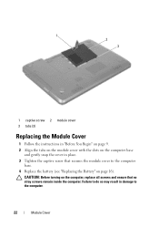
Failure to do so may result in place. 3 Tighten the captive screw that no stray screws remain inside the computer. 1 2 3 1 captive screw 2 module cover 3 tabs (3) Replacing the Module Cover 1 Follow the instructions in "Before You Begin" on page 9. 2 Align the tabs on the module cover with the slots on the computer base and gently snap the cover in damage to the computer base. 4 Replace the battery (see "Replacing the Battery" on the computer, replace all screws and ensure that secures the module cover to the computer. 22 Module Cover CAUTION: Before turning on page 16).
Failure to do so may result in place. 3 Tighten the captive screw that no stray screws remain inside the computer. 1 2 3 1 captive screw 2 module cover 3 tabs (3) Replacing the Module Cover 1 Follow the instructions in "Before You Begin" on page 9. 2 Align the tabs on the module cover with the slots on the computer base and gently snap the cover in damage to the computer base. 4 Replace the battery (see "Replacing the Battery" on the computer, replace all screws and ensure that secures the module cover to the computer. 22 Module Cover CAUTION: Before turning on page 16).
Service Manual
Page 24
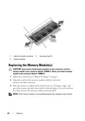
1 3 2 1 memory-module connector 2 securing clips (2) 3 memory module Replacing the Memory Module(s) CAUTION: If you need to install memory modules in two connectors, install a memory module in the memory-module connector. 3 Slide the memory module firmly into place. NOTE: If the memory module is not installed properly, the computer may not boot. 24 Memory If you install a memory module in the connector labeled "DIMM B." 1 Follow the instructions in "Before You Begin" on page 9. 2 Align the notch in the memory module with...
1 3 2 1 memory-module connector 2 securing clips (2) 3 memory module Replacing the Memory Module(s) CAUTION: If you need to install memory modules in two connectors, install a memory module in the memory-module connector. 3 Slide the memory module firmly into place. NOTE: If the memory module is not installed properly, the computer may not boot. 24 Memory If you install a memory module in the connector labeled "DIMM B." 1 Follow the instructions in "Before You Begin" on page 9. 2 Align the notch in the memory module with...
Service Manual
Page 48
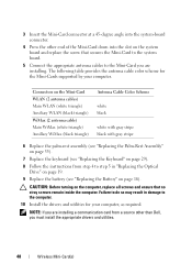
... triangle) Auxillary WiMax (black triangle) Antenna Cable Color Scheme white black white with gray stripe black with gray stripe 6 Replace the palm-rest assembly (see "Replacing the Palm-Rest Assembly" on page 35). 7 Replace the keyboard (see "Replacing the Keyboard" on page 29). 8 Follow the instructions from a source other than Dell, you must install the appropriate drivers and utilities. 48 Wireless Mini-Card(s) The following table provides...
... triangle) Auxillary WiMax (black triangle) Antenna Cable Color Scheme white black white with gray stripe black with gray stripe 6 Replace the palm-rest assembly (see "Replacing the Palm-Rest Assembly" on page 35). 7 Replace the keyboard (see "Replacing the Keyboard" on page 29). 8 Follow the instructions from a source other than Dell, you must install the appropriate drivers and utilities. 48 Wireless Mini-Card(s) The following table provides...
Service Manual
Page 49
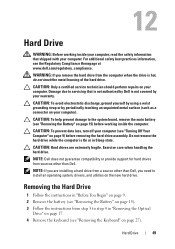
... 9. 2 Remove the battery (see "Turning Off Your Computer" on page 27). Hard Drive 49 Damage due to install an operating system, drivers, and utilities on your computer. CAUTION: To prevent data loss, turn off your computer). CAUTION: Only a certified service technician should perform repairs on the new hard drive. Do not remove the hard drive while the computer is On or in "Removing the Optical Drive" on page 17. 4 Remove the keyboard...
... 9. 2 Remove the battery (see "Turning Off Your Computer" on page 27). Hard Drive 49 Damage due to install an operating system, drivers, and utilities on your computer. CAUTION: To prevent data loss, turn off your computer). CAUTION: Only a certified service technician should perform repairs on the new hard drive. Do not remove the hard drive while the computer is On or in "Removing the Optical Drive" on page 17. 4 Remove the keyboard...
Service Manual
Page 51
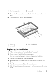
... the hard drive. 3 Place the hard drive in "Before You Begin" on the system board. Hard Drive 51 1 hard-drive assembly 2 screws (3) 9 Remove the four screws that secure the hard-drive bracket to the hard drive. 5 Place the hard-drive assembly on the computer base. 6 Slide the hard-drive assembly to connect it to the hard drive. 10 Lift the hard-drive bracket off the hard drive. 3 2 1 1 hard drive 3 screws (4) 2 hard-drive bracket Replacing the Hard Drive 1 Follow the instructions in the hard-drive bracket. 4 Replace...
... the hard drive. 3 Place the hard drive in "Before You Begin" on the system board. Hard Drive 51 1 hard-drive assembly 2 screws (3) 9 Remove the four screws that secure the hard-drive bracket to the hard drive. 5 Place the hard-drive assembly on the computer base. 6 Slide the hard-drive assembly to connect it to the hard drive. 10 Lift the hard-drive bracket off the hard drive. 3 2 1 1 hard drive 3 screws (4) 2 hard-drive bracket Replacing the Hard Drive 1 Follow the instructions in the hard-drive bracket. 4 Replace...
Service Manual
Page 72
... system board. 11 Replace the thermal fan (see "Replacing the Thermal Fan" on page 66). 12 Follow the instructions from step 5 to step 7 in "Replacing the Hard Drive" on page 51. 13 Replace the palm-rest assembly (see "Replacing the Palm-Rest Assembly" on page 35). 14 Replace the keyboard (see "Removing the Processor Module" on page 29). 72 System Board 16 Remove the coin-cell battery (see "Removing...
... system board. 11 Replace the thermal fan (see "Replacing the Thermal Fan" on page 66). 12 Follow the instructions from step 5 to step 7 in "Replacing the Hard Drive" on page 51. 13 Replace the palm-rest assembly (see "Replacing the Palm-Rest Assembly" on page 35). 14 Replace the keyboard (see "Removing the Processor Module" on page 29). 72 System Board 16 Remove the coin-cell battery (see "Removing...


