Setup Guide
Page 5
Contents Setting Up Your Inspiron Laptop 5 Before Setting Up Your Computer 5 Connect the AC Adapter 6 Connect the Network Cable (Optional 7 Press the ... Enable or Disable Wireless (Optional 12 Set Up Wireless Display (Optional 14 Connect to the Internet (Optional 16 Using Your Inspiron Laptop 18 Right View Features 18 Left View Features 20 Back View Features 24 Front View Features 26 Status Lights... Drive 38 Display Features 40 Touch Screen Gestures (Optional 42 Removing and Replacing the Top Cover (Optional 44 Removing and Replacing the Battery 48 Software Features 50...
Contents Setting Up Your Inspiron Laptop 5 Before Setting Up Your Computer 5 Connect the AC Adapter 6 Connect the Network Cable (Optional 7 Press the ... Enable or Disable Wireless (Optional 12 Set Up Wireless Display (Optional 14 Connect to the Internet (Optional 16 Using Your Inspiron Laptop 18 Right View Features 18 Left View Features 20 Back View Features 24 Front View Features 26 Status Lights... Drive 38 Display Features 40 Touch Screen Gestures (Optional 42 Removing and Replacing the Top Cover (Optional 44 Removing and Replacing the Battery 48 Software Features 50...
Setup Guide
Page 46
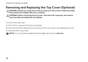
... remove external cables (including the AC adapter). NOTE: You can purchase additional replaceable top covers at dell.com. 44 Press and hold the release button that shipped with your computer. Using Your Inspiron Laptop Removing and Replacing the Top Cover (Optional) WARNING: Before you begin any of the procedures in this section, follow the...
... remove external cables (including the AC adapter). NOTE: You can purchase additional replaceable top covers at dell.com. 44 Press and hold the release button that shipped with your computer. Using Your Inspiron Laptop Removing and Replacing the Top Cover (Optional) WARNING: Before you begin any of the procedures in this section, follow the...
Setup Guide
Page 47
Using Your Inspiron Laptop 1 top cover 2 release button 3 back of the computer 3 2 1 45
Using Your Inspiron Laptop 1 top cover 2 release button 3 back of the computer 3 2 1 45
Setup Guide
Page 48
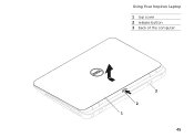
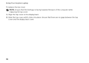
Using Your Inspiron Laptop To replace the top cover: NOTE: Ensure that there are no gaps between the top cover and the display back cover. 46 Ensure that the Dell logo is facing towards the back of the computer while replacing the top cover. 1. Align the top cover on the display back. 2. Slide the top cover until it clicks into place.
Using Your Inspiron Laptop To replace the top cover: NOTE: Ensure that there are no gaps between the top cover and the display back cover. 46 Ensure that the Dell logo is facing towards the back of the computer while replacing the top cover. 1. Align the top cover on the display back. 2. Slide the top cover until it clicks into place.
Setup Guide
Page 56
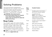
INSPIRON Solving Problems This section provides troubleshooting information for your problem using the following guidelines, see "Using Support Tools" on page 63 or "Contacting Dell" on page 83) for advanced service instructions. NOTE: To replace parts, see "Contacting Dell" on page 83. Beep Code ...support.dell.com. BIOS ROM checksum failure No RAM detected NOTE: If you cannot solve your computer. If you installed or replaced the memory module, ensure that the memory module is seated properly. WARNING: Only trained service personnel should remove the computer cover. ...
INSPIRON Solving Problems This section provides troubleshooting information for your problem using the following guidelines, see "Using Support Tools" on page 63 or "Contacting Dell" on page 83) for advanced service instructions. NOTE: To replace parts, see "Contacting Dell" on page 83. Beep Code ...support.dell.com. BIOS ROM checksum failure No RAM detected NOTE: If you cannot solve your computer. If you installed or replaced the memory module, ensure that the memory module is seated properly. WARNING: Only trained service personnel should remove the computer cover. ...

Service Manual
Page 3
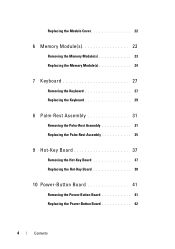
Contents 1 Before You Begin 9 Recommended Tools 9 Turning Off Your Computer 9 Before Working Inside Your Computer 10 2 Top Cover 13 Removing the Top Cover 13 Replacing the Top Cover 14 3 Battery 15 Removing the Battery 15 Replacing the Battery 16 4 Optical Drive 17 Removing the Optical Drive 17 Replacing the Optical Drive 19 5 Module Cover 21 Removing the Module Cover 21 Contents 3
Contents 1 Before You Begin 9 Recommended Tools 9 Turning Off Your Computer 9 Before Working Inside Your Computer 10 2 Top Cover 13 Removing the Top Cover 13 Replacing the Top Cover 14 3 Battery 15 Removing the Battery 15 Replacing the Battery 16 4 Optical Drive 17 Removing the Optical Drive 17 Replacing the Optical Drive 19 5 Module Cover 21 Removing the Module Cover 21 Contents 3
Service Manual
Page 4
Replacing the Module Cover 22 6 Memory Module(s 23 Removing the Memory Module(s 23 Replacing the Memory Module(s 24 7 Keyboard 27 Removing the Keyboard 27 Replacing the Keyboard 29 8 Palm-Rest Assembly 31 Removing the Palm-Rest Assembly 31 Replacing the Palm-Rest Assembly 35 9 Hot-Key Board 37 Removing the Hot-Key Board 37 Replacing the Hot-Key Board 38 10 Power-Button Board 41 Removing the Power-Button Board 41 Replacing the Power-Button Board 42 4 Contents
Replacing the Module Cover 22 6 Memory Module(s 23 Removing the Memory Module(s 23 Replacing the Memory Module(s 24 7 Keyboard 27 Removing the Keyboard 27 Replacing the Keyboard 29 8 Palm-Rest Assembly 31 Removing the Palm-Rest Assembly 31 Replacing the Palm-Rest Assembly 35 9 Hot-Key Board 37 Removing the Hot-Key Board 37 Replacing the Hot-Key Board 38 10 Power-Button Board 41 Removing the Power-Button Board 41 Replacing the Power-Button Board 42 4 Contents
Service Manual
Page 7
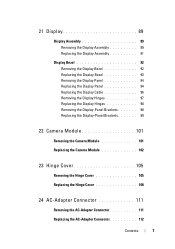
... 98 Replacing the Display-Panel Brackets 99 22 Camera Module 101 Removing the Camera Module 101 Replacing the Camera Module 102 23 Hinge Cover 105 Removing the Hinge Cover 105 Replacing the Hinge Cover 108 24 AC-Adapter Connector 111 Removing the AC-Adapter Connector 111 Replacing the AC-Adapter Connector 112 Contents 7
... 98 Replacing the Display-Panel Brackets 99 22 Camera Module 101 Removing the Camera Module 101 Replacing the Camera Module 102 23 Hinge Cover 105 Removing the Hinge Cover 105 Replacing the Hinge Cover 108 24 AC-Adapter Connector 111 Removing the AC-Adapter Connector 111 Replacing the AC-Adapter Connector 112 Contents 7
Service Manual
Page 10
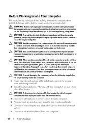
... a cable, ensure that the work surface is not covered by its pins. WARNING: Before working inside your computer, read the safety information that is not authorized by Dell is flat and clean to prevent the computer cover from potential damage and to ensure your computer (see ...the Regulatory Compliance Homepage at dell.com/regulatory_compliance. CAUTION: When you disconnect a cable, pull on its...
... a cable, ensure that the work surface is not covered by its pins. WARNING: Before working inside your computer, read the safety information that is not authorized by Dell is flat and clean to prevent the computer cover from potential damage and to ensure your computer (see ...the Regulatory Compliance Homepage at dell.com/regulatory_compliance. CAUTION: When you disconnect a cable, pull on its...

Service Manual
Page 13
... service technician should perform repairs on page 15) before working inside the computer. 2 Top Cover WARNING: Before working inside your computer, read the safety information that is not authorized by Dell is not covered by periodically touching an unpainted metal surface (such as a connector on page 9. 2 Press... and hold the release button that secures the top cover to the system board, remove the main battery (see...
... service technician should perform repairs on page 15) before working inside the computer. 2 Top Cover WARNING: Before working inside your computer, read the safety information that is not authorized by Dell is not covered by periodically touching an unpainted metal surface (such as a connector on page 9. 2 Press... and hold the release button that secures the top cover to the system board, remove the main battery (see...
Service Manual
Page 14
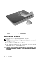
... no gaps between the top cover and display back cover. NOTE: Ensure that the DELL logo is facing towards the back of the computer while replacing the top cover. 2 Align the top cover with the display back cover. 3 Slide the top cover until it clicks into place. 2 1 1 top cover 2 release button Replacing the Top Cover 1 Follow the instructions in...
... no gaps between the top cover and display back cover. NOTE: Ensure that the DELL logo is facing towards the back of the computer while replacing the top cover. 2 Align the top cover with the display back cover. 3 Slide the top cover until it clicks into place. 2 1 1 top cover 2 release button Replacing the Top Cover 1 Follow the instructions in...

Service Manual
Page 15
... bay. CAUTION: To avoid damage to servicing that shipped with your computer. Do not use only the battery designed for other Dell computers. Removing the Battery 1 Follow the instructions in "Before You Begin" on your computer. Damage due to the computer, ... safety best practices information, see the Regulatory Compliance Homepage at dell.com/regulatory_compliance. Battery 15 3 Battery WARNING: Before working inside your computer, read the safety information that is not authorized by Dell is not covered by periodically touching an unpainted metal surface (such as a connector...
... bay. CAUTION: To avoid damage to servicing that shipped with your computer. Do not use only the battery designed for other Dell computers. Removing the Battery 1 Follow the instructions in "Before You Begin" on your computer. Damage due to the computer, ... safety best practices information, see the Regulatory Compliance Homepage at dell.com/regulatory_compliance. Battery 15 3 Battery WARNING: Before working inside your computer, read the safety information that is not authorized by Dell is not covered by periodically touching an unpainted metal surface (such as a connector...

Service Manual
Page 17
... in "Before You Begin" on page 9. 2 Remove the battery (see the Regulatory Compliance Homepage at www.dell.com/regulatory_compliance. 4 Optical Drive WARNING: Before working inside your computer, read the safety information that is not authorized by Dell is not covered by periodically touching an unpainted metal surface (such as a connector on your computer.
... in "Before You Begin" on page 9. 2 Remove the battery (see the Regulatory Compliance Homepage at www.dell.com/regulatory_compliance. 4 Optical Drive WARNING: Before working inside your computer, read the safety information that is not authorized by Dell is not covered by periodically touching an unpainted metal surface (such as a connector on your computer.

Service Manual
Page 21
... by using a wrist grounding strap or by your computer). Module Cover 21 5 Module Cover WARNING: Before working inside your computer, read the safety information that is not authorized by Dell is not covered by periodically touching an unpainted metal surface (such as a connector...damage to servicing that shipped with your computer. Removing the Module Cover 1 Follow the instructions in "Before You Begin" on page 9. 2 Remove the battery (see the Regulatory Compliance Homepage at www.dell.com/regulatory_compliance. For additional safety best practices information, see "Removing...
... by using a wrist grounding strap or by your computer). Module Cover 21 5 Module Cover WARNING: Before working inside your computer, read the safety information that is not authorized by Dell is not covered by periodically touching an unpainted metal surface (such as a connector...damage to servicing that shipped with your computer. Removing the Module Cover 1 Follow the instructions in "Before You Begin" on page 9. 2 Remove the battery (see the Regulatory Compliance Homepage at www.dell.com/regulatory_compliance. For additional safety best practices information, see "Removing...
Service Manual
Page 22
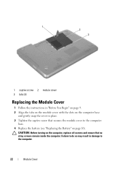
Failure to do so may result in place. 3 Tighten the captive screw that secures the module cover to the computer. 22 Module Cover 1 2 3 1 captive screw 2 module cover 3 tabs (3) Replacing the Module Cover 1 Follow the instructions in "Before You Begin" on page 9. 2 Align the tabs on the module cover with the slots on the computer base and gently snap the cover in damage to the computer base. 4 Replace the battery (see "Replacing the Battery" on the computer, replace all screws and ensure that no stray screws remain inside the computer. CAUTION: Before turning on page 16).
Failure to do so may result in place. 3 Tighten the captive screw that secures the module cover to the computer. 22 Module Cover 1 2 3 1 captive screw 2 module cover 3 tabs (3) Replacing the Module Cover 1 Follow the instructions in "Before You Begin" on page 9. 2 Align the tabs on the module cover with the slots on the computer base and gently snap the cover in damage to the computer base. 4 Replace the battery (see "Replacing the Battery" on the computer, replace all screws and ensure that no stray screws remain inside the computer. CAUTION: Before turning on page 16).

Service Manual
Page 23
... from the memory-module connector. NOTE: Memory modules purchased from Dell are covered under your computer memory by installing memory modules on page 21). For additional safety best practices information, see "Removing the Module Cover" on the system board. CAUTION: Only a certified service technician... your warranty. Your computer has two user-accessible SODIMM sockets, labeled DIMM A and DIMM B, that is not authorized by Dell is not covered by your Setup Guide for information on each end of memory supported by periodically touching an unpainted metal surface (such as a...
... from the memory-module connector. NOTE: Memory modules purchased from Dell are covered under your computer memory by installing memory modules on page 21). For additional safety best practices information, see "Removing the Module Cover" on the system board. CAUTION: Only a certified service technician... your warranty. Your computer has two user-accessible SODIMM sockets, labeled DIMM A and DIMM B, that is not authorized by Dell is not covered by your Setup Guide for information on each end of memory supported by periodically touching an unpainted metal surface (such as a...

Service Manual
Page 25
...;System. To confirm the amount of memory installed in damage to your computer and an electrical outlet. 2 1 1 tab 2 notch 4 Replace the module cover (see "Replacing the Module Cover" on page 22). 5 Replace the battery (see "Replacing the Battery" on page 16), or connect the AC adapter to the computer. 6 Turn on...
...;System. To confirm the amount of memory installed in damage to your computer and an electrical outlet. 2 1 1 tab 2 notch 4 Replace the module cover (see "Replacing the Module Cover" on page 22). 5 Replace the battery (see "Replacing the Battery" on page 16), or connect the AC adapter to the computer. 6 Turn on...
Service Manual
Page 27
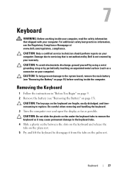
... keyboard to replace. 7 Keyboard WARNING: Before working inside your computer, read the safety information that is not authorized by Dell is not covered by periodically touching an unpainted metal surface (such as possible. For additional safety best practices information, see "Removing the Battery...remove the main battery (see "Removing the Battery" on page 9. 2 Remove the battery (see the Regulatory Compliance Homepage at www.dell.com/regulatory_compliance. Removing the Keyboard 1 Follow the instructions in "Before You Begin" on page 15) before working inside the computer....
... keyboard to replace. 7 Keyboard WARNING: Before working inside your computer, read the safety information that is not authorized by Dell is not covered by periodically touching an unpainted metal surface (such as possible. For additional safety best practices information, see "Removing the Battery...remove the main battery (see "Removing the Battery" on page 9. 2 Remove the battery (see the Regulatory Compliance Homepage at www.dell.com/regulatory_compliance. Removing the Keyboard 1 Follow the instructions in "Before You Begin" on page 15) before working inside the computer....
Service Manual
Page 31
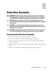
8 Palm-Rest Assembly WARNING: Before working inside your computer, read the safety information that is not authorized by Dell is not covered by periodically touching an unpainted metal surface (such as a connector on your computer). Damage due to servicing that shipped with your computer.... the keyboard (see "Removing the Battery" on page 27). For additional safety best practices information, see the Regulatory Compliance Homepage at dell.com/regulatory_compliance. CAUTION: To avoid electrostatic discharge, ground yourself by using a wrist grounding strap or by your warranty.
8 Palm-Rest Assembly WARNING: Before working inside your computer, read the safety information that is not authorized by Dell is not covered by periodically touching an unpainted metal surface (such as a connector on your computer). Damage due to servicing that shipped with your computer.... the keyboard (see "Removing the Battery" on page 27). For additional safety best practices information, see the Regulatory Compliance Homepage at dell.com/regulatory_compliance. CAUTION: To avoid electrostatic discharge, ground yourself by using a wrist grounding strap or by your warranty.

Service Manual
Page 37
... palm-rest assembly over. 7 Carefully peel the hot-key board cable from the palm-rest assembly. 8 Remove the screw that is not authorized by Dell is not covered by periodically touching an unpainted metal surface (such as a connector on page 15) before working inside the computer. 9 Hot-Key Board WARNING: Before working...
... palm-rest assembly over. 7 Carefully peel the hot-key board cable from the palm-rest assembly. 8 Remove the screw that is not authorized by Dell is not covered by periodically touching an unpainted metal surface (such as a connector on page 15) before working inside the computer. 9 Hot-Key Board WARNING: Before working...


