
Service Manual
Page 5
11 Wireless Mini-Card(s 45 Removing the Mini-Card(s 45 Replacing the Mini-Card(s 47 12 Hard Drive 49 Removing the Hard Drive 49 Replacing the Hard Drive 51 A Subwoofer 53 Removing the Subwoofer 53 Replacing the Subwoofer 54 13 Status Light Board 57 Removing the Status Light Board 57 Replacing the Status Light Board 58 14 Speakers 61 Removing the Speakers 61 Replacing the Speakers 62 15 Thermal Fan 65 Removing the Thermal Fan 65 Contents 5
11 Wireless Mini-Card(s 45 Removing the Mini-Card(s 45 Replacing the Mini-Card(s 47 12 Hard Drive 49 Removing the Hard Drive 49 Replacing the Hard Drive 51 A Subwoofer 53 Removing the Subwoofer 53 Replacing the Subwoofer 54 13 Status Light Board 57 Removing the Status Light Board 57 Replacing the Status Light Board 58 14 Speakers 61 Removing the Speakers 61 Replacing the Speakers 62 15 Thermal Fan 65 Removing the Thermal Fan 65 Contents 5
Service Manual
Page 6
Replacing the Thermal Fan 66 16 System Board 69 Removing the System Board 69 Replacing the System Board 72 Entering the Service Tag in the BIOS 73 17 Coin-Cell Battery 75 Removing the Coin-Cell Battery 75 Replacing the Coin-Cell Battery 76 18 I/O Board 79 Removing the I/O Board 79 Replacing the I/O Board 80 19 Thermal Cooling Assembly 81 Removing the Thermal Cooling Assembly 81 Replacing the Thermal Cooling Assembly 82 20 Processor Module 85 Removing the Processor Module 85 Replacing the Processor Module 86 6 Contents
Replacing the Thermal Fan 66 16 System Board 69 Removing the System Board 69 Replacing the System Board 72 Entering the Service Tag in the BIOS 73 17 Coin-Cell Battery 75 Removing the Coin-Cell Battery 75 Replacing the Coin-Cell Battery 76 18 I/O Board 79 Removing the I/O Board 79 Replacing the I/O Board 80 19 Thermal Cooling Assembly 81 Removing the Thermal Cooling Assembly 81 Replacing the Thermal Cooling Assembly 82 20 Processor Module 85 Removing the Processor Module 85 Replacing the Processor Module 86 6 Contents

Service Manual
Page 66
3 1 3 2 1 screws (2) 3 thermal-fan cable 2 thermal fan Replacing the Thermal Fan 1 Follow the procedures in "Before You Begin" on page 9. 2 Place the thermal fan on the computer base and replace the two screws that secure the thermal fan to the computer base. 3 Connect the thermal-fan cable to the connector on the system board. 4 Replace the palm-rest assembly (see "Replacing the Palm-Rest Assembly" on page 35). 66 Thermal Fan
3 1 3 2 1 screws (2) 3 thermal-fan cable 2 thermal fan Replacing the Thermal Fan 1 Follow the procedures in "Before You Begin" on page 9. 2 Place the thermal fan on the computer base and replace the two screws that secure the thermal fan to the computer base. 3 Connect the thermal-fan cable to the connector on the system board. 4 Replace the palm-rest assembly (see "Replacing the Palm-Rest Assembly" on page 35). 66 Thermal Fan

Service Manual
Page 67
Failure to do so may result in damage to step 5 in "Replacing the Optical Drive" on page 19. 7 Replace the battery (see "Replacing the Keyboard" on page 29). 6 Follow the instructions from step 4 to the computer. Thermal Fan 67 5 Replace the keyboard (see "Replacing the Battery" on page 16). CAUTION: Before turning on the computer, replace all screws and ensure that no stray screws remain inside the computer.
Failure to do so may result in damage to step 5 in "Replacing the Optical Drive" on page 19. 7 Replace the battery (see "Replacing the Keyboard" on page 29). 6 Follow the instructions from step 4 to the computer. Thermal Fan 67 5 Replace the keyboard (see "Replacing the Battery" on page 16). CAUTION: Before turning on the computer, replace all screws and ensure that no stray screws remain inside the computer.
Service Manual
Page 72
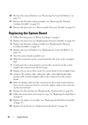
... the computer base. 7 Gently press the system board to connect the connector on the system board to the connector on the I/O board. 8 Replace the six screws that secure the system board to the computer base. 9 Connect the speaker cable, subwoofer cable, status-light board cable, camera ...on the system board. 11 Replace the thermal fan (see "Replacing the Thermal Fan" on page 66). 12 Follow the instructions from step 5 to step 7 in "Replacing the Hard Drive" on page 51. 13 Replace the palm-rest assembly (see "Replacing the Palm-Rest Assembly" on page 35). 14 Replace the keyboard (see "Removing...
... the computer base. 7 Gently press the system board to connect the connector on the system board to the connector on the I/O board. 8 Replace the six screws that secure the system board to the computer base. 9 Connect the speaker cable, subwoofer cable, status-light board cable, camera ...on the system board. 11 Replace the thermal fan (see "Replacing the Thermal Fan" on page 66). 12 Follow the instructions from step 5 to step 7 in "Replacing the Hard Drive" on page 51. 13 Replace the palm-rest assembly (see "Replacing the Palm-Rest Assembly" on page 35). 14 Replace the keyboard (see "Removing...

Service Manual
Page 112
...connector to the computer base. 12 Lift the AC-adapter connector off the computer base. 2 1 1 screw 2 AC-adapter connector cable Replacing the AC-Adapter Connector 1 Follow the instructions in "Before You Begin" on page 9. 2 Place the AC-adapter connector on the computer base and...the AC-adapter connector cable through the routing guide. 4 Connect the AC-adapter connector cable to the connector on the system board. 5 Replace the display assembly (see "Replacing the Display Assembly" on page 91). 6 Replace the thermal fan (see "Replacing the Thermal Fan" on page 66). 112 AC-Adapter Connector
...connector to the computer base. 12 Lift the AC-adapter connector off the computer base. 2 1 1 screw 2 AC-adapter connector cable Replacing the AC-Adapter Connector 1 Follow the instructions in "Before You Begin" on page 9. 2 Place the AC-adapter connector on the computer base and...the AC-adapter connector cable through the routing guide. 4 Connect the AC-adapter connector cable to the connector on the system board. 5 Replace the display assembly (see "Replacing the Display Assembly" on page 91). 6 Replace the thermal fan (see "Replacing the Thermal Fan" on page 66). 112 AC-Adapter Connector


