Setup Guide
Page 5
...Recommended 10 Enable or Disable Wireless (Optional 12 Set Up Wireless Display (Optional 14 Connect to the Internet (Optional 16 Using Your Inspiron Laptop 18 Right View Features 18 Left View Features 20 Back View Features 24 Front View Features 26 Status Lights and... Battery Charging 29 Computer Base and Keyboard Features 30 Touch Pad Gestures 34 Multimedia Control Keys 36 Using the Optical Drive 38 Display Features 40 Touch Screen Gestures (Optional 42 Removing and Replacing the Top Cover (Optional 44 Removing and Replacing the Battery 48 Software Features 50 Dell ...
...Recommended 10 Enable or Disable Wireless (Optional 12 Set Up Wireless Display (Optional 14 Connect to the Internet (Optional 16 Using Your Inspiron Laptop 18 Right View Features 18 Left View Features 20 Back View Features 24 Front View Features 26 Status Lights and... Battery Charging 29 Computer Base and Keyboard Features 30 Touch Pad Gestures 34 Multimedia Control Keys 36 Using the Optical Drive 38 Display Features 40 Touch Screen Gestures (Optional 42 Removing and Replacing the Top Cover (Optional 44 Removing and Replacing the Battery 48 Software Features 50 Dell ...

Setup Guide
Page 50
...). This computer should only use batteries from Dell. Turn off the computer and turn it clicks into place. 2. Slide and lift the battery out of the procedures in this section, follow the safety instructions that shipped with your computer. To remove the battery: 1. Using Your Inspiron Laptop Removing and Replacing the Battery WARNING: Before you begin any...
...). This computer should only use batteries from Dell. Turn off the computer and turn it clicks into place. 2. Slide and lift the battery out of the procedures in this section, follow the safety instructions that shipped with your computer. To remove the battery: 1. Using Your Inspiron Laptop Removing and Replacing the Battery WARNING: Before you begin any...

Service Manual
Page 3
Contents 1 Before You Begin 9 Recommended Tools 9 Turning Off Your Computer 9 Before Working Inside Your Computer 10 2 Top Cover 13 Removing the Top Cover 13 Replacing the Top Cover 14 3 Battery 15 Removing the Battery 15 Replacing the Battery 16 4 Optical Drive 17 Removing the Optical Drive 17 Replacing the Optical Drive 19 5 Module Cover 21 Removing the Module Cover 21 Contents 3
Contents 1 Before You Begin 9 Recommended Tools 9 Turning Off Your Computer 9 Before Working Inside Your Computer 10 2 Top Cover 13 Removing the Top Cover 13 Replacing the Top Cover 14 3 Battery 15 Removing the Battery 15 Replacing the Battery 16 4 Optical Drive 17 Removing the Optical Drive 17 Replacing the Optical Drive 19 5 Module Cover 21 Removing the Module Cover 21 Contents 3
Service Manual
Page 6
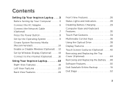
Replacing the Thermal Fan 66 16 System Board 69 Removing the System Board 69 Replacing the System Board 72 Entering the Service Tag in the BIOS 73 17 Coin-Cell Battery 75 Removing the Coin-Cell Battery 75 Replacing the Coin-Cell Battery 76 18 I/O Board 79 Removing the I/O Board 79 Replacing the I/O Board 80 19 Thermal Cooling Assembly 81 Removing the Thermal Cooling Assembly 81 Replacing the Thermal Cooling Assembly 82 20 Processor Module 85 Removing the Processor Module 85 Replacing the Processor Module 86 6 Contents
Replacing the Thermal Fan 66 16 System Board 69 Removing the System Board 69 Replacing the System Board 72 Entering the Service Tag in the BIOS 73 17 Coin-Cell Battery 75 Removing the Coin-Cell Battery 75 Replacing the Coin-Cell Battery 76 18 I/O Board 79 Removing the I/O Board 79 Replacing the I/O Board 80 19 Thermal Cooling Assembly 81 Removing the Thermal Cooling Assembly 81 Replacing the Thermal Cooling Assembly 82 20 Processor Module 85 Removing the Processor Module 85 Replacing the Processor Module 86 6 Contents

Service Manual
Page 16
3 2 1 1 battery release latch 2 battery 3 battery lock latch Replacing the Battery 1 Follow the instructions in "Before You Begin" on page 9. 2 Slide the battery into the battery bay until it clicks into place. 3 Slide the battery lock latch to the lock position. 16 Battery
3 2 1 1 battery release latch 2 battery 3 battery lock latch Replacing the Battery 1 Follow the instructions in "Before You Begin" on page 9. 2 Slide the battery into the battery bay until it clicks into place. 3 Slide the battery lock latch to the lock position. 16 Battery

Service Manual
Page 19
3 1 2 1 optical-drive bracket 3 optical-drive bezel 2 optical drive Replacing the Optical Drive 1 Follow the instructions in "Before You Begin" on page 9. 2 Align the tabs on the optical-drive bezel with the slots on the ...-drive bracket with the screw holes on the optical drive and replace the two screws. 4 Slide the optical-drive assembly into the optical-drive compartment until it is fully seated. 5 Replace the screw that secures the optical-drive assembly to the computer base. 6 Replace the battery (see "Replacing the Battery" on page 16). Optical Drive 19
3 1 2 1 optical-drive bracket 3 optical-drive bezel 2 optical drive Replacing the Optical Drive 1 Follow the instructions in "Before You Begin" on page 9. 2 Align the tabs on the optical-drive bezel with the slots on the ...-drive bracket with the screw holes on the optical drive and replace the two screws. 4 Slide the optical-drive assembly into the optical-drive compartment until it is fully seated. 5 Replace the screw that secures the optical-drive assembly to the computer base. 6 Replace the battery (see "Replacing the Battery" on page 16). Optical Drive 19
Service Manual
Page 22
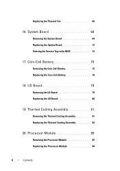
CAUTION: Before turning on page 16). 1 2 3 1 captive screw 2 module cover 3 tabs (3) Replacing the Module Cover 1 Follow the instructions in "Before You Begin" on page 9. 2 Align the tabs on the module cover with the slots on the computer base and gently snap the cover in damage to the computer base. 4 Replace the battery (see "Replacing the Battery" on the computer, replace all screws and ensure that secures the module cover to the computer. 22 Module Cover Failure to do so may result in place. 3 Tighten the captive screw that no stray screws remain inside the computer.
CAUTION: Before turning on page 16). 1 2 3 1 captive screw 2 module cover 3 tabs (3) Replacing the Module Cover 1 Follow the instructions in "Before You Begin" on page 9. 2 Align the tabs on the module cover with the slots on the computer base and gently snap the cover in damage to the computer base. 4 Replace the battery (see "Replacing the Battery" on the computer, replace all screws and ensure that secures the module cover to the computer. 22 Module Cover Failure to do so may result in place. 3 Tighten the captive screw that no stray screws remain inside the computer.

Service Manual
Page 25
...Start Control PanelSystem and SecuritySystem. 2 1 1 tab 2 notch 4 Replace the module cover (see "Replacing the Module Cover" on page 22). 5 Replace the battery (see "Replacing the Battery" on page 16), or connect the AC adapter to the computer. 6 Turn on the computer..., replace all screws and ensure that no stray screws remain inside the computer. CAUTION: Before turning on the computer...
...Start Control PanelSystem and SecuritySystem. 2 1 1 tab 2 notch 4 Replace the module cover (see "Replacing the Module Cover" on page 22). 5 Replace the battery (see "Replacing the Battery" on page 16), or connect the AC adapter to the computer. 6 Turn on the computer..., replace all screws and ensure that no stray screws remain inside the computer. CAUTION: Before turning on the computer...
Service Manual
Page 27
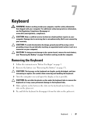
... 15) before working inside the computer. Damage due to the system board, remove the main battery (see the Regulatory Compliance Homepage at www.dell.com/regulatory_compliance. CAUTION: To avoid electrostatic discharge, ground yourself by using a wrist grounding strap or... by your computer. Be careful when removing and handling the keyboard. 3 Turn the computer over and open the display as far as a connector on the plam rest. 5 Pry and lift the keyboard to replace...
... 15) before working inside the computer. Damage due to the system board, remove the main battery (see the Regulatory Compliance Homepage at www.dell.com/regulatory_compliance. CAUTION: To avoid electrostatic discharge, ground yourself by using a wrist grounding strap or... by your computer. Be careful when removing and handling the keyboard. 3 Turn the computer over and open the display as far as a connector on the plam rest. 5 Pry and lift the keyboard to replace...

Service Manual
Page 30
6 Replace the battery (see "Replacing the Battery" on page 16). 30 Keyboard
6 Replace the battery (see "Replacing the Battery" on page 16). 30 Keyboard

Service Manual
Page 35
... the palm rest assembly with the slots on the computer base and gently snap the palm rest assembly in "Replacing the Optical Drive" on page 19. 11 Replace the battery (see "Replacing the Battery" on the computer, replace all screws and ensure that no stray screws remain inside the computer. CAUTION: Before turning on page 16...
... the palm rest assembly with the slots on the computer base and gently snap the palm rest assembly in "Replacing the Optical Drive" on page 19. 11 Replace the battery (see "Replacing the Battery" on the computer, replace all screws and ensure that no stray screws remain inside the computer. CAUTION: Before turning on page 16...

Service Manual
Page 39
Failure to do so may result in damage to step 5 in "Replacing the Optical Drive" on page 19. 8 Replace the battery (see "Replacing the Battery" on the computer, replace all screws and ensure that no stray screws remain inside the computer. Hot-Key Board 39 CAUTION: Before turning on page 16). 7 Follow the instructions from step 4 to the computer.
Failure to do so may result in damage to step 5 in "Replacing the Optical Drive" on page 19. 8 Replace the battery (see "Replacing the Battery" on the computer, replace all screws and ensure that no stray screws remain inside the computer. Hot-Key Board 39 CAUTION: Before turning on page 16). 7 Follow the instructions from step 4 to the computer.

Service Manual
Page 43
Power-Button Board 43 CAUTION: Before turning on page 16). 8 Follow the instructions from step 4 to the computer. Failure to do so may result in damage to step 5 in "Replacing the Optical Drive" on page 19. 9 Replace the battery (see "Replacing the Battery" on the computer, replace all screws and ensure that no stray screws remain inside the computer.
Power-Button Board 43 CAUTION: Before turning on page 16). 8 Follow the instructions from step 4 to the computer. Failure to do so may result in damage to step 5 in "Replacing the Optical Drive" on page 19. 9 Replace the battery (see "Replacing the Battery" on the computer, replace all screws and ensure that no stray screws remain inside the computer.
Service Manual
Page 48
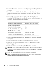
3 Insert the Mini-Card connector at a 45-degree angle into the system-board connector. 4 Press the other than Dell, you are installing a communication card from step 4 to step 5 in damage to the Mini-Card you must install the appropriate drivers and utilities.... Cable Color Scheme white black white with gray stripe black with gray stripe 6 Replace the palm-rest assembly (see "Replacing the Palm-Rest Assembly" on page 35). 7 Replace the keyboard (see "Replacing the Battery" on the system board and replace the screw that no stray screws remain inside the computer. Failure to do so...
3 Insert the Mini-Card connector at a 45-degree angle into the system-board connector. 4 Press the other than Dell, you are installing a communication card from step 4 to step 5 in damage to the Mini-Card you must install the appropriate drivers and utilities.... Cable Color Scheme white black white with gray stripe black with gray stripe 6 Replace the palm-rest assembly (see "Replacing the Palm-Rest Assembly" on page 35). 7 Replace the keyboard (see "Replacing the Battery" on the system board and replace the screw that no stray screws remain inside the computer. Failure to do so...

Service Manual
Page 52
CAUTION: Before turning on the computer, replace all screws and ensure that secure the hard-drive assembly to the computer base. 8 Replace the palm-rest assembly (see "Replacing the Palm-Rest Assembly" on page 35). 9 Replace the keyboard (see "Replacing the Keyboard" on page 29). 10 Follow the instructions from step 4 to step 5 in damage to do so may result in "Replacing the Optical Drive" on page 19. 11 Replace the battery (see "Replacing the Battery" on page 16). Failure to the computer. 52 Hard Drive 7 Replace the three screws that no stray screws remain inside the computer.
CAUTION: Before turning on the computer, replace all screws and ensure that secure the hard-drive assembly to the computer base. 8 Replace the palm-rest assembly (see "Replacing the Palm-Rest Assembly" on page 35). 9 Replace the keyboard (see "Replacing the Keyboard" on page 29). 10 Follow the instructions from step 4 to step 5 in damage to do so may result in "Replacing the Optical Drive" on page 19. 11 Replace the battery (see "Replacing the Battery" on page 16). Failure to the computer. 52 Hard Drive 7 Replace the three screws that no stray screws remain inside the computer.

Service Manual
Page 55
Failure to the computer. Speaker Assembly 55 6 Follow the instructions from step 4 to step 5 in damage to do so may result in "Replacing the Optical Drive" on page 19. 7 Replace the battery (see "Replacing the Battery" on the computer, replace all screws and ensure that no stray screws remain inside the computer. CAUTION: Before turning on page 16).
Failure to the computer. Speaker Assembly 55 6 Follow the instructions from step 4 to step 5 in damage to do so may result in "Replacing the Optical Drive" on page 19. 7 Replace the battery (see "Replacing the Battery" on the computer, replace all screws and ensure that no stray screws remain inside the computer. CAUTION: Before turning on page 16).

Service Manual
Page 59
5 Replace the palm-rest assembly (see "Replacing the Palm-Rest Assembly" on page 35). 6 Replace the keyboard (see "Replacing the Battery" on page 16). Failure to do so may result in damage to step 5 in "Replacing the Optical Drive" on page 19. 8 Replace the battery (see "Replacing the Keyboard" on the computer, replace all screws and ensure that no stray screws remain inside the computer. Status Light Board 59 CAUTION: Before turning on page 29). 7 Follow the instructions from step 4 to the computer.
5 Replace the palm-rest assembly (see "Replacing the Palm-Rest Assembly" on page 35). 6 Replace the keyboard (see "Replacing the Battery" on page 16). Failure to do so may result in damage to step 5 in "Replacing the Optical Drive" on page 19. 8 Replace the battery (see "Replacing the Keyboard" on the computer, replace all screws and ensure that no stray screws remain inside the computer. Status Light Board 59 CAUTION: Before turning on page 29). 7 Follow the instructions from step 4 to the computer.

Service Manual
Page 63
Speakers 63 Failure to do so may result in damage to step 5 in "Replacing the Optical Drive" on page 19. 8 Replace the battery (see "Replacing the Keyboard" on page 29). 7 Follow the instructions from step 4 to the computer. CAUTION: Before turning on the computer, replace all screws and ensure that no stray screws remain inside the computer. 5 Replace the palm-rest assembly (see "Replacing the Palm-Rest Assembly" on page 35). 6 Replace the keyboard (see "Replacing the Battery" on page 16).
Speakers 63 Failure to do so may result in damage to step 5 in "Replacing the Optical Drive" on page 19. 8 Replace the battery (see "Replacing the Keyboard" on page 29). 7 Follow the instructions from step 4 to the computer. CAUTION: Before turning on the computer, replace all screws and ensure that no stray screws remain inside the computer. 5 Replace the palm-rest assembly (see "Replacing the Palm-Rest Assembly" on page 35). 6 Replace the keyboard (see "Replacing the Battery" on page 16).

Service Manual
Page 67
5 Replace the keyboard (see "Replacing the Battery" on the computer, replace all screws and ensure that no stray screws remain inside the computer. Thermal Fan 67 CAUTION: Before turning on page 16). Failure to do so may result in "Replacing the Optical Drive" on page 19. 7 Replace the battery (see "Replacing the Keyboard" on page 29). 6 Follow the instructions from step 4 to step 5 in damage to the computer.
5 Replace the keyboard (see "Replacing the Battery" on the computer, replace all screws and ensure that no stray screws remain inside the computer. Thermal Fan 67 CAUTION: Before turning on page 16). Failure to do so may result in "Replacing the Optical Drive" on page 19. 7 Replace the battery (see "Replacing the Keyboard" on page 29). 6 Follow the instructions from step 4 to step 5 in damage to the computer.
Service Manual
Page 72
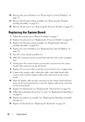
... Board 1 Follow the instructions in "Before You Begin" on page 9. 2 Replace the processor (see "Replacing the Processor Module" on page 86). 3 Replace the thermal cooling assembly (see "Replacing the Thermal Cooling Assembly" on page 82). 4 Replace the coin-cell battery (see "Replacing the Coin-Cell Battery" on page 76). 5 Turn the system board assembly over. 6 Slide the connectors...
... Board 1 Follow the instructions in "Before You Begin" on page 9. 2 Replace the processor (see "Replacing the Processor Module" on page 86). 3 Replace the thermal cooling assembly (see "Replacing the Thermal Cooling Assembly" on page 82). 4 Replace the coin-cell battery (see "Replacing the Coin-Cell Battery" on page 76). 5 Turn the system board assembly over. 6 Slide the connectors...


