Setup Guide
Page 7
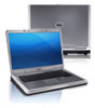
...Placing or stacking heavy or sharp objects on the computer may cause it is normal and does not indicate a problem with the fan or the computer. You should never place your laptop may result in an enclosed space, such as carpets or rugs, while ... inches) on all other sides. Before Setting Up Your Computer When positioning your Dell Inspiron laptop. Restricting the airflow can damage the computer, deteriorate the computer performance, or cause a fire. INSPIRON Setting Up Your Inspiron Laptop This section provides information about setting up your computer, ensure that you allow ...
...Placing or stacking heavy or sharp objects on the computer may cause it is normal and does not indicate a problem with the fan or the computer. You should never place your laptop may result in an enclosed space, such as carpets or rugs, while ... inches) on all other sides. Before Setting Up Your Computer When positioning your Dell Inspiron laptop. Restricting the airflow can damage the computer, deteriorate the computer performance, or cause a fire. INSPIRON Setting Up Your Inspiron Laptop This section provides information about setting up your computer, ensure that you allow ...

Service Manual
Page 5
11 Wireless Mini-Card(s 45 Removing the Mini-Card(s 45 Replacing the Mini-Card(s 47 12 Hard Drive 49 Removing the Hard Drive 49 Replacing the Hard Drive 51 A Subwoofer 53 Removing the Subwoofer 53 Replacing the Subwoofer 54 13 Status Light Board 57 Removing the Status Light Board 57 Replacing the Status Light Board 58 14 Speakers 61 Removing the Speakers 61 Replacing the Speakers 62 15 Thermal Fan 65 Removing the Thermal Fan 65 Contents 5
11 Wireless Mini-Card(s 45 Removing the Mini-Card(s 45 Replacing the Mini-Card(s 47 12 Hard Drive 49 Removing the Hard Drive 49 Replacing the Hard Drive 51 A Subwoofer 53 Removing the Subwoofer 53 Replacing the Subwoofer 54 13 Status Light Board 57 Removing the Status Light Board 57 Replacing the Status Light Board 58 14 Speakers 61 Removing the Speakers 61 Replacing the Speakers 62 15 Thermal Fan 65 Removing the Thermal Fan 65 Contents 5
Service Manual
Page 6
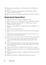
Replacing the Thermal Fan 66 16 System Board 69 Removing the System Board 69 Replacing the System Board 72 Entering the Service Tag in the BIOS 73 17 Coin-Cell Battery 75 Removing the Coin-Cell Battery 75 Replacing the Coin-Cell Battery 76 18 I/O Board 79 Removing the I/O Board 79 Replacing the I/O Board 80 19 Thermal Cooling Assembly 81 Removing the Thermal Cooling Assembly 81 Replacing the Thermal Cooling Assembly 82 20 Processor Module 85 Removing the Processor Module 85 Replacing the Processor Module 86 6 Contents
Replacing the Thermal Fan 66 16 System Board 69 Removing the System Board 69 Replacing the System Board 72 Entering the Service Tag in the BIOS 73 17 Coin-Cell Battery 75 Removing the Coin-Cell Battery 75 Replacing the Coin-Cell Battery 76 18 I/O Board 79 Removing the I/O Board 79 Replacing the I/O Board 80 19 Thermal Cooling Assembly 81 Removing the Thermal Cooling Assembly 81 Replacing the Thermal Cooling Assembly 82 20 Processor Module 85 Removing the Processor Module 85 Replacing the Processor Module 86 6 Contents

Service Manual
Page 65
...CAUTION: Only a certified service technician should perform repairs on your computer). Thermal Fan 65 16 Thermal Fan WARNING: Before working inside your computer, read the safety information that is not authorized by Dell is not covered by periodically touching an unpainted metal surface (such as a ... page 31). 6 Disconnect the thermal-fan cable from the connector on the system board. 7 Remove the two screws that secure the thermal fan to the system board, remove the main battery (see the Regulatory Compliance Homepage at dell.com/regulatory_compliance. For additional safety best ...
...CAUTION: Only a certified service technician should perform repairs on your computer). Thermal Fan 65 16 Thermal Fan WARNING: Before working inside your computer, read the safety information that is not authorized by Dell is not covered by periodically touching an unpainted metal surface (such as a ... page 31). 6 Disconnect the thermal-fan cable from the connector on the system board. 7 Remove the two screws that secure the thermal fan to the system board, remove the main battery (see the Regulatory Compliance Homepage at dell.com/regulatory_compliance. For additional safety best ...

Service Manual
Page 66
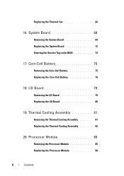
3 1 3 2 1 screws (2) 3 thermal-fan cable 2 thermal fan Replacing the Thermal Fan 1 Follow the procedures in "Before You Begin" on page 9. 2 Place the thermal fan on the computer base and replace the two screws that secure the thermal fan to the computer base. 3 Connect the thermal-fan cable to the connector on the system board. 4 Replace the palm-rest assembly (see "Replacing the Palm-Rest Assembly" on page 35). 66 Thermal Fan
3 1 3 2 1 screws (2) 3 thermal-fan cable 2 thermal fan Replacing the Thermal Fan 1 Follow the procedures in "Before You Begin" on page 9. 2 Place the thermal fan on the computer base and replace the two screws that secure the thermal fan to the computer base. 3 Connect the thermal-fan cable to the connector on the system board. 4 Replace the palm-rest assembly (see "Replacing the Palm-Rest Assembly" on page 35). 66 Thermal Fan

Service Manual
Page 67
CAUTION: Before turning on page 16). Thermal Fan 67 Failure to the computer. 5 Replace the keyboard (see "Replacing the Keyboard" on page 29). 6 Follow the instructions from step 4 to step 5 in damage to do so may result in "Replacing the Optical Drive" on page 19. 7 Replace the battery (see "Replacing the Battery" on the computer, replace all screws and ensure that no stray screws remain inside the computer.
CAUTION: Before turning on page 16). Thermal Fan 67 Failure to the computer. 5 Replace the keyboard (see "Replacing the Keyboard" on page 29). 6 Follow the instructions from step 4 to step 5 in damage to do so may result in "Replacing the Optical Drive" on page 19. 7 Replace the battery (see "Replacing the Battery" on the computer, replace all screws and ensure that no stray screws remain inside the computer.

Service Manual
Page 68
68 Thermal Fan
68 Thermal Fan
Service Manual
Page 70
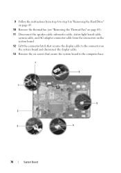
9 Follow the instructions from step 6 to step 8 in "Removing the Hard Drive" on page 49. 10 Remove the thermal fan (see "Removing the Thermal Fan" on page 65). 11 Disconnect the speaker cable, subwoofer cable, status-light board cable, camera cable, and AC-adapter connector cable from the connectors on the system board. 12 Lift the connector latch that secures the display cable to the connector on the system board and disconnect the display cable. 13 Remove the six screws that secure the system board to the computer base. 7 6 1 5 2 3 4 70 System Board
9 Follow the instructions from step 6 to step 8 in "Removing the Hard Drive" on page 49. 10 Remove the thermal fan (see "Removing the Thermal Fan" on page 65). 11 Disconnect the speaker cable, subwoofer cable, status-light board cable, camera cable, and AC-adapter connector cable from the connectors on the system board. 12 Lift the connector latch that secures the display cable to the connector on the system board and disconnect the display cable. 13 Remove the six screws that secure the system board to the computer base. 7 6 1 5 2 3 4 70 System Board
Service Manual
Page 72
... and press down on the connector latch to secure the display cable to the connector on the system board. 11 Replace the thermal fan (see "Replacing the Thermal Fan" on page 66). 12 Follow the instructions from step 5 to step 7 in "Replacing the Hard Drive" on page 51. 13 Replace the palm...
... and press down on the connector latch to secure the display cable to the connector on the system board. 11 Replace the thermal fan (see "Replacing the Thermal Fan" on page 66). 12 Follow the instructions from step 5 to step 7 in "Replacing the Hard Drive" on page 51. 13 Replace the palm...
Service Manual
Page 111
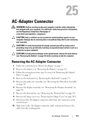
...Rest Assembly" on page 31). 6 Remove the display assembly (see "Removing the Display Assembly" on page 89). 7 Remove the thermal fan (see "Removing the Thermal Fan" on page 65). 8 Remove the hinge cover (see "Removing the Hinge Cover" on page 105). 9 Disconnect the AC-adapter connector...page 15). 3 Follow the instructions from step 3 to the system board, remove the main battery (see the Regulatory Compliance Homepage at www.dell.com/regulatory_compliance. CAUTION: To avoid electrostatic discharge, ground yourself by using a wrist grounding strap or by your warranty. AC-Adapter Connector 111...
...Rest Assembly" on page 31). 6 Remove the display assembly (see "Removing the Display Assembly" on page 89). 7 Remove the thermal fan (see "Removing the Thermal Fan" on page 65). 8 Remove the hinge cover (see "Removing the Hinge Cover" on page 105). 9 Disconnect the AC-adapter connector...page 15). 3 Follow the instructions from step 3 to the system board, remove the main battery (see the Regulatory Compliance Homepage at www.dell.com/regulatory_compliance. CAUTION: To avoid electrostatic discharge, ground yourself by using a wrist grounding strap or by your warranty. AC-Adapter Connector 111...

Service Manual
Page 112
...-adapter connector cable to the connector on the system board. 5 Replace the display assembly (see "Replacing the Display Assembly" on page 91). 6 Replace the thermal fan (see "Replacing the Thermal Fan" on page 66). 112 AC-Adapter Connector
...-adapter connector cable to the connector on the system board. 5 Replace the display assembly (see "Replacing the Display Assembly" on page 91). 6 Replace the thermal fan (see "Replacing the Thermal Fan" on page 66). 112 AC-Adapter Connector


