Setup Guide
Page 5
...the Internet (Optional 16 Using Your Inspiron Laptop 18 Right View Features 18 Left View Features 20 Back View Features 24 Front View Features 26 Status Lights and Indicators 28 Disabling Battery Charging 29 Computer Base and Keyboard Features 30 Touch Pad Gestures 34 ...Multimedia Control Keys 36 Using the Optical Drive 38 Display Features 40 Touch Screen Gestures (Optional 42 Removing and Replacing the Top Cover (Optional 44 Removing and Replacing the Battery 48 Software Features 50 Dell DataSafe Online Backup 51 Dell...
...the Internet (Optional 16 Using Your Inspiron Laptop 18 Right View Features 18 Left View Features 20 Back View Features 24 Front View Features 26 Status Lights and Indicators 28 Disabling Battery Charging 29 Computer Base and Keyboard Features 30 Touch Pad Gestures 34 ...Multimedia Control Keys 36 Using the Optical Drive 38 Display Features 40 Touch Screen Gestures (Optional 42 Removing and Replacing the Top Cover (Optional 44 Removing and Replacing the Battery 48 Software Features 50 Dell DataSafe Online Backup 51 Dell...
Setup Guide
Page 21
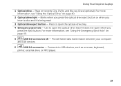
...optional). Provide faster data transmission between your computer and USB devices. 6 USB 2.0 connector - Using Your Inspiron Laptop 1 Optical drive - Press to open the optical-drive tray if it is being read. 3 Optical... For more information, see "Using the Emergency Eject Hole" on page 40. 2 Optical drive light - Blinks when you press the optical drive eject button or when you insert a disc and it.... 4 Emergency eject hole - Use to USB devices, such as a mouse, keyboard, printer, external drive, or MP3 player. 19 For more information, see "Using the Optical Drive" on page ...
...optional). Provide faster data transmission between your computer and USB devices. 6 USB 2.0 connector - Using Your Inspiron Laptop 1 Optical drive - Press to open the optical-drive tray if it is being read. 3 Optical... For more information, see "Using the Emergency Eject Hole" on page 40. 2 Optical drive light - Blinks when you press the optical drive eject button or when you insert a disc and it.... 4 Emergency eject hole - Use to USB devices, such as a mouse, keyboard, printer, external drive, or MP3 player. 19 For more information, see "Using the Optical Drive" on page ...
Setup Guide
Page 33
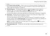
...keyboard. 4 Touch pad buttons (2) - NOTE: To enable or disable the touch pad, press along with the < > key on the function key row on the button indicates the power states. To change the touch pad settings, double-click the Dell Touch pad icon in this row. Using Your Inspiron Laptop 1 Power button and light... - For more information on the multimedia keys, see "Status Lights and Indicators" on or off your desktop. Provide left -...
...keyboard. 4 Touch pad buttons (2) - NOTE: To enable or disable the touch pad, press along with the < > key on the function key row on the button indicates the power states. To change the touch pad settings, double-click the Dell Touch pad icon in this row. Using Your Inspiron Laptop 1 Power button and light... - For more information on the multimedia keys, see "Status Lights and Indicators" on or off your desktop. Provide left -...
Setup Guide
Page 59
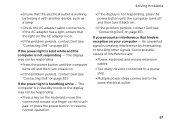
...on page 83). If the power light is solid white and the computer is creating interference by testing it back on. • If the problem persists, contact Dell (see "Contacting Dell" on page 83). Some possible causes of interference are: • Power, keyboard, and mouse extension cables. •...turn it back on. • If the problem persists, contact Dell (see "Contacting Dell" on page 83). An unwanted signal is not responding - If the power light is on. • If the problem persists, contact Dell (see "Contacting Dell" on your computer - Solving Problems • Ensure that the...
...on page 83). If the power light is solid white and the computer is creating interference by testing it back on. • If the problem persists, contact Dell (see "Contacting Dell" on page 83). Some possible causes of interference are: • Power, keyboard, and mouse extension cables. •...turn it back on. • If the problem persists, contact Dell (see "Contacting Dell" on page 83). An unwanted signal is not responding - If the power light is on. • If the problem persists, contact Dell (see "Contacting Dell" on your computer - Solving Problems • Ensure that the...
Service Manual
Page 57
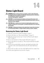
...or by your computer. Damage due to the connector on your computer. 14 Status Light Board WARNING: Before working inside your computer, read the safety information that is not authorized by Dell is not covered by periodically touching an unpainted metal surface (such as a connector... the Keyboard" on page 27). 5 Remove the palm-rest assembly (see "Removing the Palm-Rest Assembly" on page 31). 6 Lift the connector latch that secures the status light board to the system board, remove the main battery (see the Regulatory Compliance Homepage at www.dell.com/regulatory_compliance...
...or by your computer. Damage due to the connector on your computer. 14 Status Light Board WARNING: Before working inside your computer, read the safety information that is not authorized by Dell is not covered by periodically touching an unpainted metal surface (such as a connector... the Keyboard" on page 27). 5 Remove the palm-rest assembly (see "Removing the Palm-Rest Assembly" on page 31). 6 Lift the connector latch that secures the status light board to the system board, remove the main battery (see the Regulatory Compliance Homepage at www.dell.com/regulatory_compliance...

Service Manual
Page 59
Status Light Board 59 Failure to do so may result in damage to step 5 in "Replacing the Optical Drive" on page 19. 8 Replace the battery (see "Replacing the Battery" on page 16). CAUTION: Before turning on the computer, replace all screws and ensure that no stray screws remain inside the computer. 5 Replace the palm-rest assembly (see "Replacing the Palm-Rest Assembly" on page 35). 6 Replace the keyboard (see "Replacing the Keyboard" on page 29). 7 Follow the instructions from step 4 to the computer.
Status Light Board 59 Failure to do so may result in damage to step 5 in "Replacing the Optical Drive" on page 19. 8 Replace the battery (see "Replacing the Battery" on page 16). CAUTION: Before turning on the computer, replace all screws and ensure that no stray screws remain inside the computer. 5 Replace the palm-rest assembly (see "Replacing the Palm-Rest Assembly" on page 35). 6 Replace the keyboard (see "Replacing the Keyboard" on page 29). 7 Follow the instructions from step 4 to the computer.
Service Manual
Page 61
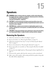
...Speakers WARNING: Before working inside your computer, read the safety information that is not authorized by Dell is not covered by periodically touching an unpainted metal surface (such as a connector on your...the Speakers 1 Follow the instructions in "Removing the Optical Drive" on page 17. 4 Remove the keyboard (see "Removing the Keyboard" on page 27). 5 Remove the palm-rest assembly (see "Removing the Palm-Rest Assembly" on... safety best practices information, see "Removing the Status Light Board" on page 57). 7 Disconnect the speaker cable from the connector on page 31). 6 Remove the...
...Speakers WARNING: Before working inside your computer, read the safety information that is not authorized by Dell is not covered by periodically touching an unpainted metal surface (such as a connector on your...the Speakers 1 Follow the instructions in "Removing the Optical Drive" on page 17. 4 Remove the keyboard (see "Removing the Keyboard" on page 27). 5 Remove the palm-rest assembly (see "Removing the Palm-Rest Assembly" on... safety best practices information, see "Removing the Status Light Board" on page 57). 7 Disconnect the speaker cable from the connector on page 31). 6 Remove the...
Service Manual
Page 72
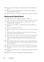
...connector on the I/O board. 8 Replace the six screws that secure the system board to the computer base. 9 Connect the speaker cable, subwoofer cable, status-light board cable, camera cable, and AC-adapter cable to the connectors on the system board. 10 Slide the display cable into the connector on the...Replacing the Hard Drive" on page 51. 13 Replace the palm-rest assembly (see "Replacing the Palm-Rest Assembly" on page 35). 14 Replace the keyboard (see "Removing the Processor Module" on page 29). 72 System Board 16 Remove the coin-cell battery (see "Removing the Coin-Cell Battery" on page...
...connector on the I/O board. 8 Replace the six screws that secure the system board to the computer base. 9 Connect the speaker cable, subwoofer cable, status-light board cable, camera cable, and AC-adapter cable to the connectors on the system board. 10 Slide the display cable into the connector on the...Replacing the Hard Drive" on page 51. 13 Replace the palm-rest assembly (see "Replacing the Palm-Rest Assembly" on page 35). 14 Replace the keyboard (see "Removing the Processor Module" on page 29). 72 System Board 16 Remove the coin-cell battery (see "Removing the Coin-Cell Battery" on page...


