
Setup Guide
Page 84
INSPIRON Finding More Information and Resources If you need to contact technical support the bottom of your computer may void your warranty. Check your warranty and return policies before working inside your Service Tag/Express Service Code - You must use the service tag to identify your computer on support.dell...support.dell.com upgrade your computer with new or additional components like a new hard drive reinstall or replace a worn or defective part the Service Manual at support.dell.com/manuals NOTE: In some countries, opening and replacing parts of your computer "Dell Support...
INSPIRON Finding More Information and Resources If you need to contact technical support the bottom of your computer may void your warranty. Check your warranty and return policies before working inside your Service Tag/Express Service Code - You must use the service tag to identify your computer on support.dell...support.dell.com upgrade your computer with new or additional components like a new hard drive reinstall or replace a worn or defective part the Service Manual at support.dell.com/manuals NOTE: In some countries, opening and replacing parts of your computer "Dell Support...

Service Manual
Page 5
11 Wireless Mini-Card(s 45 Removing the Mini-Card(s 45 Replacing the Mini-Card(s 47 12 Hard Drive 49 Removing the Hard Drive 49 Replacing the Hard Drive 51 A Subwoofer 53 Removing the Subwoofer 53 Replacing the Subwoofer 54 13 Status Light Board 57 Removing the Status Light Board 57 Replacing the Status Light Board 58 14 Speakers 61 Removing the Speakers 61 Replacing the Speakers 62 15 Thermal Fan 65 Removing the Thermal Fan 65 Contents 5
11 Wireless Mini-Card(s 45 Removing the Mini-Card(s 45 Replacing the Mini-Card(s 47 12 Hard Drive 49 Removing the Hard Drive 49 Replacing the Hard Drive 51 A Subwoofer 53 Removing the Subwoofer 53 Replacing the Subwoofer 54 13 Status Light Board 57 Removing the Status Light Board 57 Replacing the Status Light Board 58 14 Speakers 61 Removing the Speakers 61 Replacing the Speakers 62 15 Thermal Fan 65 Removing the Thermal Fan 65 Contents 5
Service Manual
Page 51
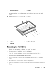
... the hard drive. 5 Place the hard-drive assembly on the computer base. 6 Slide the hard-drive assembly to connect it to the hard drive. 10 Lift the hard-drive bracket off the hard drive. 3 2 1 1 hard drive 3 screws (4) 2 hard-drive bracket Replacing the Hard Drive 1 Follow the instructions in the hard-drive bracket. 4 Replace the four screws that secure the hard-drive bracket to the connector on page 9. 2 Remove the new hard drive from its packaging. Hard Drive 51...
... the hard drive. 5 Place the hard-drive assembly on the computer base. 6 Slide the hard-drive assembly to connect it to the hard drive. 10 Lift the hard-drive bracket off the hard drive. 3 2 1 1 hard drive 3 screws (4) 2 hard-drive bracket Replacing the Hard Drive 1 Follow the instructions in the hard-drive bracket. 4 Replace the four screws that secure the hard-drive bracket to the connector on page 9. 2 Remove the new hard drive from its packaging. Hard Drive 51...

Service Manual
Page 52
7 Replace the three screws that no stray screws remain inside the computer. Failure to do so may result in damage to step 5 in "Replacing the Optical Drive" on page 19. 11 Replace the battery (see "Replacing the Battery" on page 29). 10 Follow the instructions from step 4 to the computer. 52 Hard Drive CAUTION: Before turning on the computer, replace all screws and ensure that secure the hard-drive assembly to the computer base. 8 Replace the palm-rest assembly (see "Replacing the Palm-Rest Assembly" on page 35). 9 Replace the keyboard (see "Replacing the Keyboard" on page 16).
7 Replace the three screws that no stray screws remain inside the computer. Failure to do so may result in damage to step 5 in "Replacing the Optical Drive" on page 19. 11 Replace the battery (see "Replacing the Battery" on page 29). 10 Follow the instructions from step 4 to the computer. 52 Hard Drive CAUTION: Before turning on the computer, replace all screws and ensure that secure the hard-drive assembly to the computer base. 8 Replace the palm-rest assembly (see "Replacing the Palm-Rest Assembly" on page 35). 9 Replace the keyboard (see "Replacing the Keyboard" on page 16).
Service Manual
Page 72
...on the computer base. 7 Gently press the system board to connect the connector on the system board to the connector on the I/O board. 8 Replace the six screws that secure the system board to the computer base. 9 Connect the speaker cable, subwoofer cable, status-light board cable, camera cable... Fan" on page 66). 12 Follow the instructions from step 5 to step 7 in "Replacing the Hard Drive" on page 51. 13 Replace the palm-rest assembly (see "Replacing the Palm-Rest Assembly" on page 35). 14 Replace the keyboard (see "Removing the Processor Module" on page 29). 72 System Board 16 Remove...
...on the computer base. 7 Gently press the system board to connect the connector on the system board to the connector on the I/O board. 8 Replace the six screws that secure the system board to the computer base. 9 Connect the speaker cable, subwoofer cable, status-light board cable, camera cable... Fan" on page 66). 12 Follow the instructions from step 5 to step 7 in "Replacing the Hard Drive" on page 51. 13 Replace the palm-rest assembly (see "Replacing the Palm-Rest Assembly" on page 35). 14 Replace the keyboard (see "Removing the Processor Module" on page 29). 72 System Board 16 Remove...


