Setup Guide
Page 5
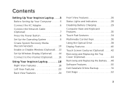
Contents Setting Up Your Inspiron Laptop 5 Before Setting Up Your Computer 5 Connect the AC Adapter 6 Connect the Network ...Disable Wireless (Optional 12 Set Up Wireless Display (Optional 14 Connect to the Internet (Optional 16 Using Your Inspiron Laptop 18 Right View Features 18 Left View Features 20 Back View Features 24 Front View Features... 26 Status Lights and Indicators 28 Disabling Battery Charging 29 Computer Base and Keyboard Features 30 Touch Pad Gestures 34 Multimedia Control Keys 36 Using the Optical Drive 38 Display Features 40 ...
Contents Setting Up Your Inspiron Laptop 5 Before Setting Up Your Computer 5 Connect the AC Adapter 6 Connect the Network ...Disable Wireless (Optional 12 Set Up Wireless Display (Optional 14 Connect to the Internet (Optional 16 Using Your Inspiron Laptop 18 Right View Features 18 Left View Features 20 Back View Features 24 Front View Features... 26 Status Lights and Indicators 28 Disabling Battery Charging 29 Computer Base and Keyboard Features 30 Touch Pad Gestures 34 Multimedia Control Keys 36 Using the Optical Drive 38 Display Features 40 ...
Service Manual
Page 4
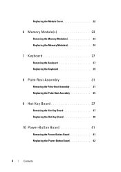
Replacing the Module Cover 22 6 Memory Module(s 23 Removing the Memory Module(s 23 Replacing the Memory Module(s 24 7 Keyboard 27 Removing the Keyboard 27 Replacing the Keyboard 29 8 Palm-Rest Assembly 31 Removing the Palm-Rest Assembly 31 Replacing the Palm-Rest Assembly 35 9 Hot-Key Board 37 Removing the Hot-Key Board 37 Replacing the Hot-Key Board 38 10 Power-Button Board 41 Removing the Power-Button Board 41 Replacing the Power-Button Board 42 4 Contents
Replacing the Module Cover 22 6 Memory Module(s 23 Removing the Memory Module(s 23 Replacing the Memory Module(s 24 7 Keyboard 27 Removing the Keyboard 27 Replacing the Keyboard 29 8 Palm-Rest Assembly 31 Removing the Palm-Rest Assembly 31 Replacing the Palm-Rest Assembly 35 9 Hot-Key Board 37 Removing the Hot-Key Board 37 Replacing the Hot-Key Board 38 10 Power-Button Board 41 Removing the Power-Button Board 41 Replacing the Power-Button Board 42 4 Contents
Service Manual
Page 27
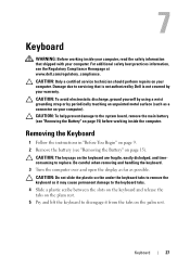
...the display as far as a connector on page 15) before working inside the computer. 7 Keyboard WARNING: Before working inside your computer, read the safety information that is not authorized by Dell is not covered by periodically touching an unpainted metal surface (such as possible. CAUTION: To ... computer). CAUTION: Do not slide the plastic scribe under the keyboard tabs to remove the keyboard as it may cause permanent damage to the keyboard tabs. 4 Slide a plastic scribe between the slots on the keyboard and release the tabs on the plam rest. 5 Pry and lift the keyboard to replace.
...the display as far as a connector on page 15) before working inside the computer. 7 Keyboard WARNING: Before working inside your computer, read the safety information that is not authorized by Dell is not covered by periodically touching an unpainted metal surface (such as possible. CAUTION: To ... computer). CAUTION: Do not slide the plastic scribe under the keyboard tabs to remove the keyboard as it may cause permanent damage to the keyboard tabs. 4 Slide a plastic scribe between the slots on the keyboard and release the tabs on the plam rest. 5 Pry and lift the keyboard to replace.

Service Manual
Page 29
Press down on the connector latch to secure the keyboard cable to the connector on the system board. 3 Slide the tabs on the keyboard into the connector on the palm rest. 5 Close the display and turn the computer over. Keyboard 29 1 2 1 keyboard cable 2 keyboard-cable connector Replacing the Keyboard 1 Follow the instructions in "Before You Begin" on page 9. 2 Slide the keyboard cable into the slots on the palm rest. 4 Gently press around the edges of the keyboard and slide it upwards to secure the keyboard under the tabs on the system board.
Press down on the connector latch to secure the keyboard cable to the connector on the system board. 3 Slide the tabs on the keyboard into the connector on the palm rest. 5 Close the display and turn the computer over. Keyboard 29 1 2 1 keyboard cable 2 keyboard-cable connector Replacing the Keyboard 1 Follow the instructions in "Before You Begin" on page 9. 2 Slide the keyboard cable into the slots on the palm rest. 4 Gently press around the edges of the keyboard and slide it upwards to secure the keyboard under the tabs on the system board.

Service Manual
Page 30
6 Replace the battery (see "Replacing the Battery" on page 16). 30 Keyboard
6 Replace the battery (see "Replacing the Battery" on page 16). 30 Keyboard

Service Manual
Page 35
... 11 screws that no stray screws remain inside the computer. Replacing the Palm-Rest Assembly 1 Follow the instructions in "Before You Begin" on page 9. 2 Replace the hot-key board (see "Replacing the Hot-Key Board" on page 38). 3 Replace the power-button board (see "Replacing the Power-Button Board" on page 42). 4 Align the tabs...-button board cable, and hot-key board cable into the connectors on the system board and press down on the connector latches to secure them. 6 Replace the four screws on the palm-rest assembly. 7 Replace the keyboard (see "Replacing the Keyboard" on page 16).
... 11 screws that no stray screws remain inside the computer. Replacing the Palm-Rest Assembly 1 Follow the instructions in "Before You Begin" on page 9. 2 Replace the hot-key board (see "Replacing the Hot-Key Board" on page 38). 3 Replace the power-button board (see "Replacing the Power-Button Board" on page 42). 4 Align the tabs...-button board cable, and hot-key board cable into the connectors on the system board and press down on the connector latches to secure them. 6 Replace the four screws on the palm-rest assembly. 7 Replace the keyboard (see "Replacing the Keyboard" on page 16).

Service Manual
Page 38
3 2 1 1 hot-key board cable 3 screw 2 hot-key board Replacing the Hot-Key Board 1 Follow the instructions in "Before You Begin" on page 9. 2 Align the screw hole on the hot-key board with the screw hole on the palm-rest assembly and replace the screw. 3 Adhere the hot-key board cable to the palm-rest assembly. 4 Turn the palm-rest assembly over. 5 Replace the palm-rest assembly (see "Replacing the Palm-Rest Assembly" on page 35). 6 Replace the keyboard (see "Replacing the Keyboard" on page 29). 38 Hot-Key Board
3 2 1 1 hot-key board cable 3 screw 2 hot-key board Replacing the Hot-Key Board 1 Follow the instructions in "Before You Begin" on page 9. 2 Align the screw hole on the hot-key board with the screw hole on the palm-rest assembly and replace the screw. 3 Adhere the hot-key board cable to the palm-rest assembly. 4 Turn the palm-rest assembly over. 5 Replace the palm-rest assembly (see "Replacing the Palm-Rest Assembly" on page 35). 6 Replace the keyboard (see "Replacing the Keyboard" on page 29). 38 Hot-Key Board

Service Manual
Page 42
1 2 3 1 screw 2 power-button board cable 3 power-button board Replacing the Power-Button Board 1 Follow the instructions in "Before You Begin" on page 9. 2 Slide the power-button board under the tab on the palm-rest assembly. 3 Replace the screw that secures the power-button board to the palm-rest assembly. 4 Adhere the power-button board cable to the palm-rest assembly. 5 Turn the palm-rest assembly over. 6 Replace the palm-rest assembly (see "Replacing the Palm-Rest Assembly" on page 35). 7 Replace the keyboard (see "Replacing the Keyboard" on page 29). 42 Power-Button Board
1 2 3 1 screw 2 power-button board cable 3 power-button board Replacing the Power-Button Board 1 Follow the instructions in "Before You Begin" on page 9. 2 Slide the power-button board under the tab on the palm-rest assembly. 3 Replace the screw that secures the power-button board to the palm-rest assembly. 4 Adhere the power-button board cable to the palm-rest assembly. 5 Turn the palm-rest assembly over. 6 Replace the palm-rest assembly (see "Replacing the Palm-Rest Assembly" on page 35). 7 Replace the keyboard (see "Replacing the Keyboard" on page 29). 42 Power-Button Board
Service Manual
Page 48
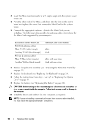
...black triangle) Antenna Cable Color Scheme white black white with gray stripe black with gray stripe 6 Replace the palm-rest assembly (see "Replacing the Palm-Rest Assembly" on page 35). 7 Replace the keyboard (see "Replacing the Keyboard" on page 29). 8 Follow the instructions from a source other end of the Mini-Card ...down into the slot on the system board and replace the screw that no stray screws remain inside the computer. 3 Insert the Mini-Card connector at a 45-degree angle into the system-board connector. 4 Press the other than Dell, you are installing.
...black triangle) Antenna Cable Color Scheme white black white with gray stripe black with gray stripe 6 Replace the palm-rest assembly (see "Replacing the Palm-Rest Assembly" on page 35). 7 Replace the keyboard (see "Replacing the Keyboard" on page 29). 8 Follow the instructions from a source other end of the Mini-Card ...down into the slot on the system board and replace the screw that no stray screws remain inside the computer. 3 Insert the Mini-Card connector at a 45-degree angle into the system-board connector. 4 Press the other than Dell, you are installing.

Service Manual
Page 52
CAUTION: Before turning on the computer, replace all screws and ensure that secure the hard-drive assembly to the computer base. 8 Replace the palm-rest assembly (see "Replacing the Palm-Rest Assembly" on page 35). 9 Replace the keyboard (see "Replacing the Battery" on page 29). 10 Follow the instructions from step 4 to the computer. 52 Hard Drive 7 Replace the three screws that no stray screws remain inside the computer. Failure to do so may result in damage to step 5 in "Replacing the Optical Drive" on page 19. 11 Replace the battery (see "Replacing the Keyboard" on page 16).
CAUTION: Before turning on the computer, replace all screws and ensure that secure the hard-drive assembly to the computer base. 8 Replace the palm-rest assembly (see "Replacing the Palm-Rest Assembly" on page 35). 9 Replace the keyboard (see "Replacing the Battery" on page 29). 10 Follow the instructions from step 4 to the computer. 52 Hard Drive 7 Replace the three screws that no stray screws remain inside the computer. Failure to do so may result in damage to step 5 in "Replacing the Optical Drive" on page 19. 11 Replace the battery (see "Replacing the Keyboard" on page 16).

Service Manual
Page 54
1 2 1 subwoofer cable 2 subwoofer Replacing the Subwoofer 1 Follow the procedures in "Before You Begin" on page 9. 2 Place the subwoofer on the computer base. 3 Connect the subwoofer cable to the connector on the system board. 4 Replace the palm-rest assembly (see "Replacing the Palm-Rest Assembly" on page 35). 5 Replace the keyboard (see "Replacing the Keyboard" on page 29). 54 Speaker Assembly
1 2 1 subwoofer cable 2 subwoofer Replacing the Subwoofer 1 Follow the procedures in "Before You Begin" on page 9. 2 Place the subwoofer on the computer base. 3 Connect the subwoofer cable to the connector on the system board. 4 Replace the palm-rest assembly (see "Replacing the Palm-Rest Assembly" on page 35). 5 Replace the keyboard (see "Replacing the Keyboard" on page 29). 54 Speaker Assembly

Service Manual
Page 59
Status Light Board 59 Failure to the computer. CAUTION: Before turning on the computer, replace all screws and ensure that no stray screws remain inside the computer. 5 Replace the palm-rest assembly (see "Replacing the Palm-Rest Assembly" on page 35). 6 Replace the keyboard (see "Replacing the Keyboard" on page 29). 7 Follow the instructions from step 4 to step 5 in damage to do so may result in "Replacing the Optical Drive" on page 19. 8 Replace the battery (see "Replacing the Battery" on page 16).
Status Light Board 59 Failure to the computer. CAUTION: Before turning on the computer, replace all screws and ensure that no stray screws remain inside the computer. 5 Replace the palm-rest assembly (see "Replacing the Palm-Rest Assembly" on page 35). 6 Replace the keyboard (see "Replacing the Keyboard" on page 29). 7 Follow the instructions from step 4 to step 5 in damage to do so may result in "Replacing the Optical Drive" on page 19. 8 Replace the battery (see "Replacing the Battery" on page 16).

Service Manual
Page 63
CAUTION: Before turning on page 16). Speakers 63 Failure to the computer. 5 Replace the palm-rest assembly (see "Replacing the Palm-Rest Assembly" on page 35). 6 Replace the keyboard (see "Replacing the Keyboard" on page 29). 7 Follow the instructions from step 4 to step 5 in damage to do so may result in "Replacing the Optical Drive" on page 19. 8 Replace the battery (see "Replacing the Battery" on the computer, replace all screws and ensure that no stray screws remain inside the computer.
CAUTION: Before turning on page 16). Speakers 63 Failure to the computer. 5 Replace the palm-rest assembly (see "Replacing the Palm-Rest Assembly" on page 35). 6 Replace the keyboard (see "Replacing the Keyboard" on page 29). 7 Follow the instructions from step 4 to step 5 in damage to do so may result in "Replacing the Optical Drive" on page 19. 8 Replace the battery (see "Replacing the Battery" on the computer, replace all screws and ensure that no stray screws remain inside the computer.

Service Manual
Page 67
Failure to do so may result in damage to step 5 in "Replacing the Optical Drive" on page 19. 7 Replace the battery (see "Replacing the Keyboard" on page 29). 6 Follow the instructions from step 4 to the computer. 5 Replace the keyboard (see "Replacing the Battery" on page 16). CAUTION: Before turning on the computer, replace all screws and ensure that no stray screws remain inside the computer. Thermal Fan 67
Failure to do so may result in damage to step 5 in "Replacing the Optical Drive" on page 19. 7 Replace the battery (see "Replacing the Keyboard" on page 29). 6 Follow the instructions from step 4 to the computer. 5 Replace the keyboard (see "Replacing the Battery" on page 16). CAUTION: Before turning on the computer, replace all screws and ensure that no stray screws remain inside the computer. Thermal Fan 67
Service Manual
Page 72
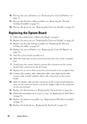
... Thermal Fan" on page 66). 12 Follow the instructions from step 5 to step 7 in "Replacing the Hard Drive" on page 51. 13 Replace the palm-rest assembly (see "Replacing the Palm-Rest Assembly" on page 35). 14 Replace the keyboard (see "Removing the Processor Module" on page 29). 72 System Board 16 Remove the coin...
... Thermal Fan" on page 66). 12 Follow the instructions from step 5 to step 7 in "Replacing the Hard Drive" on page 51. 13 Replace the palm-rest assembly (see "Replacing the Palm-Rest Assembly" on page 35). 14 Replace the keyboard (see "Removing the Processor Module" on page 29). 72 System Board 16 Remove the coin...
Service Manual
Page 92
... system board. 5 Connect the Mini-Card antenna cables to the Mini-Card(s) (see "Replacing the Mini-Card(s)" on page 47). 6 Replace the palm-rest assembly (see "Replacing the Palm-Rest Assembly" on page 35). 7 Replace the keyboard (see "Replacing the Keyboard" on page 29). 8 Replace the two screws that no stray screws remain inside edge of the display...
... system board. 5 Connect the Mini-Card antenna cables to the Mini-Card(s) (see "Replacing the Mini-Card(s)" on page 47). 6 Replace the palm-rest assembly (see "Replacing the Palm-Rest Assembly" on page 35). 7 Replace the keyboard (see "Replacing the Keyboard" on page 29). 8 Replace the two screws that no stray screws remain inside edge of the display...

Service Manual
Page 103
CAUTION: Before turning on the computer, replace all screws and ensure that no stray screws remain inside the computer. Failure to do so may result in "Replacing the Optical Drive" on page 19. 10 Replace the battery (see "Replacing the Keyboard" on page 29). 9 Follow the instructions from step 4 to step 5 in damage to the computer. Camera Module 103 7 Replace the palm-rest assembly (see "Replacing the Palm-Rest Assembly" on page 35). 8 Replace the keyboard (see "Replacing the Battery" on page 16).
CAUTION: Before turning on the computer, replace all screws and ensure that no stray screws remain inside the computer. Failure to do so may result in "Replacing the Optical Drive" on page 19. 10 Replace the battery (see "Replacing the Keyboard" on page 29). 9 Follow the instructions from step 4 to step 5 in damage to the computer. Camera Module 103 7 Replace the palm-rest assembly (see "Replacing the Palm-Rest Assembly" on page 35). 8 Replace the keyboard (see "Replacing the Battery" on page 16).

Service Manual
Page 108
... on the computer base and snap the hinge cover into place. 3 Replace the display assembly (see "Replacing the Display Assembly" on page 91). 4 Replace the palm-rest assembly (see "Replacing the Palm-Rest Assembly" on page 35). 5 Replace the keyboard (see "Replacing the Keyboard" on page 29). 6 Replace the four screws that secure the hinge cover to the computer...
... on the computer base and snap the hinge cover into place. 3 Replace the display assembly (see "Replacing the Display Assembly" on page 91). 4 Replace the palm-rest assembly (see "Replacing the Palm-Rest Assembly" on page 35). 5 Replace the keyboard (see "Replacing the Keyboard" on page 29). 6 Replace the four screws that secure the hinge cover to the computer...

Service Manual
Page 113
CAUTION: Before turning on the computer, replace all screws and ensure that no stray screws remain inside the computer. Failure to do so may result in damage to step 5 in "Replacing the Optical Drive" on page 19. 11 Replace the battery (see "Replacing the Battery" on page 16). AC-Adapter Connector 113 7 Replace the hinge cover (see "Replacing the Hinge Cover" on page 108). 8 Replace the palm-rest assembly (see "Replacing the Palm-Rest Assembly" on page 35). 9 Replace the keyboard (see "Replacing the Keyboard" on page 29). 10 Follow the instructions from step 4 to the computer.
CAUTION: Before turning on the computer, replace all screws and ensure that no stray screws remain inside the computer. Failure to do so may result in damage to step 5 in "Replacing the Optical Drive" on page 19. 11 Replace the battery (see "Replacing the Battery" on page 16). AC-Adapter Connector 113 7 Replace the hinge cover (see "Replacing the Hinge Cover" on page 108). 8 Replace the palm-rest assembly (see "Replacing the Palm-Rest Assembly" on page 35). 9 Replace the keyboard (see "Replacing the Keyboard" on page 29). 10 Follow the instructions from step 4 to the computer.


