Setup Guide
Page 6
... Problems 56 Memory Problems 58 Lockups and Software Problems 58 Using Support Tools 61 Dell Support Center 61 My Dell Downloads 62 Hardware Troubleshooter 63 Dell Diagnostics 63 Restoring Your Operating System 65 System Restore 66 Dell DataSafe Local Backup 67 System Recovery Media 70 Dell Factory Image ...Status Service 76 Product Information 76 Returning Items for Repair Under Warranty or for Credit 77 Before You Call 79 Contacting Dell 81 Finding More Information and Resources 82 Specifications 84 Appendix 91 Information for NOM, or Official Mexican Standard (Only for Mexico...
... Problems 56 Memory Problems 58 Lockups and Software Problems 58 Using Support Tools 61 Dell Support Center 61 My Dell Downloads 62 Hardware Troubleshooter 63 Dell Diagnostics 63 Restoring Your Operating System 65 System Restore 66 Dell DataSafe Local Backup 67 System Recovery Media 70 Dell Factory Image ...Status Service 76 Product Information 76 Returning Items for Repair Under Warranty or for Credit 77 Before You Call 79 Contacting Dell 81 Finding More Information and Resources 82 Specifications 84 Appendix 91 Information for NOM, or Official Mexican Standard (Only for Mexico...
Setup Guide
Page 25
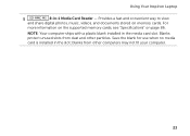
NOTE: Your computer ships with a plastic blank installed in -1 Media Card Reader - Using Your Inspiron Laptop 5 8-in the media card slot. Blanks protect unused slots from other particles. Save the blank for use when no media card is installed in the slot; For more information on the supported memory cards, see "Specifications" on memory cards. Provides a fast and convenient way to view and share digital photos, music, videos, and documents stored on page 86. blanks from dust and other computers may not fit your computer. 23
NOTE: Your computer ships with a plastic blank installed in -1 Media Card Reader - Using Your Inspiron Laptop 5 8-in the media card slot. Blanks protect unused slots from other particles. Save the blank for use when no media card is installed in the slot; For more information on the supported memory cards, see "Specifications" on memory cards. Provides a fast and convenient way to view and share digital photos, music, videos, and documents stored on page 86. blanks from dust and other computers may not fit your computer. 23
Setup Guide
Page 56
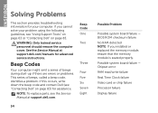
...Problem Possible system board failure - See the Service Manual at support.dell.com. Possible system board failure - If you installed or replaced the memory module, ensure that the memory module is seated properly. Beep Codes Your computer might emit a ...series of beeps during start-up if there are errors or problems. This series of beeps, called a beep code, identifies a problem. If this occurs, write down the beep code and contact Dell (see "Contacting Dell" on page 83. INSPIRON...
...Problem Possible system board failure - See the Service Manual at support.dell.com. Possible system board failure - If you installed or replaced the memory module, ensure that the memory module is seated properly. Beep Codes Your computer might emit a ...series of beeps during start-up if there are errors or problems. This series of beeps, called a beep code, identifies a problem. If this occurs, write down the beep code and contact Dell (see "Contacting Dell" on page 83. INSPIRON...
Setup Guide
Page 60
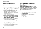
... Save and close any open files and exit any open programs you experience other memory problems - • Run Dell Diagnostics (see "Dell Diagnostics" on page 65). • If the problem persists, contact Dell (see "Contacting Dell" on page 83). If a program stops responding - Select the program that...outlet. If necessary, install additional memory (see the Service Manual at support.dell.com/manuals). • Reseat the memory module(s) into the connector(s) (see the Service Manual at support.dell.com/manuals). • If the problem persists, contact Dell (see if that the AC adapter...
... Save and close any open files and exit any open programs you experience other memory problems - • Run Dell Diagnostics (see "Dell Diagnostics" on page 65). • If the problem persists, contact Dell (see "Contacting Dell" on page 83). If a program stops responding - Select the program that...outlet. If necessary, install additional memory (see the Service Manual at support.dell.com/manuals). • Reseat the memory module(s) into the connector(s) (see the Service Manual at support.dell.com/manuals). • If the problem persists, contact Dell (see if that the AC adapter...
Setup Guide
Page 63
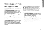
... service code, warranty status, and alerts on the day they occurred. 61 The home page also provides links to other Dell tools and diagnostic services. PC Checkup Utilities • Drive Space Manager - This utility displays all hardware scans, tests, ...→ Dell→ Dell Support Center→ Launch Dell Support Center. Run hardware diagnostics, see which program occupies the maximum memory on your hard drive using a visual representation of file. • Performance and Configuration History - one convenient location. INSPIRON Using Support Tools Dell Support Center...
... service code, warranty status, and alerts on the day they occurred. 61 The home page also provides links to other Dell tools and diagnostic services. PC Checkup Utilities • Drive Space Manager - This utility displays all hardware scans, tests, ...→ Dell→ Dell Support Center→ Launch Dell Support Center. Run hardware diagnostics, see which program occupies the maximum memory on your hard drive using a visual representation of file. • Performance and Configuration History - one convenient location. INSPIRON Using Support Tools Dell Support Center...
Setup Guide
Page 65
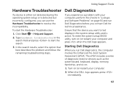
...search results, select the option that the device you contact Dell for devices such as the system board, keyboard, display, memory, hard drive, and so on (or restart) your computer and press when the Dell logo appears. When the DELL logo appears, press immediately. 63 To enter the system... setup (BIOS) utility, turn on page 60 and run Dell diagnostics, the computer invokes ...
...search results, select the option that the device you contact Dell for devices such as the system board, keyboard, display, memory, hard drive, and so on (or restart) your computer and press when the Dell logo appears. When the DELL logo appears, press immediately. 63 To enter the system... setup (BIOS) utility, turn on page 60 and run Dell diagnostics, the computer invokes ...
Setup Guide
Page 66
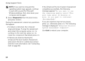
... press , otherwise press . Click Exit to reboot your computer and try again. 3. Do you want to run the remaining memory tests? then, shut down the error code(s) and contact Dell (for more . to retest the component that appear. • If a failure is displayed: "Enhanced Pre-boot System Assessment...(Recommended)." Using Support Tools NOTE: If you wait too long and the operating system logo appears, continue to wait until you see "Contacting Dell" on page 83). To stop the assessment and restart the computer, press ; This will take about 30 minutes or more information, see the...
... press , otherwise press . Click Exit to reboot your computer and try again. 3. Do you want to run the remaining memory tests? then, shut down the error code(s) and contact Dell (for more . to retest the component that appear. • If a failure is displayed: "Enhanced Pre-boot System Assessment...(Recommended)." Using Support Tools NOTE: If you wait too long and the operating system logo appears, continue to wait until you see "Contacting Dell" on page 83). To stop the assessment and restart the computer, press ; This will take about 30 minutes or more information, see the...
Setup Guide
Page 86
... may need when setting up, updating drivers for, and upgrading your computer. Computer Model Memory Dell Inspiron N7110 Computer Information System chipset Mobile Intel 6 series Processor types Intel Core i3 Intel Core i5 Intel Core i7 Memory module connector Memory module capacities Minimum memory Maximum memory two user-accessible SODIMM connectors 1 GB, 2 GB, and 4 GB 2 GB 8 GB Possible...
... may need when setting up, updating drivers for, and upgrading your computer. Computer Model Memory Dell Inspiron N7110 Computer Information System chipset Mobile Intel 6 series Processor types Intel Core i3 Intel Core i5 Intel Core i7 Memory module connector Memory module capacities Minimum memory Maximum memory two user-accessible SODIMM connectors 1 GB, 2 GB, and 4 GB 2 GB 8 GB Possible...

Setup Guide
Page 87
Memory Memory type 1333 MHz SODIMM DDR3 NOTE: For instructions on upgrading the memory, see the Service Manual at support.dell.com/manuals. Connectors Audio Mini-Card one microphone-in connector and one stereo headphones/ speakers connector two half Mini-Card slots HDMI connector one 19-pin connector Network adapter one RJ45 connector Specifications Connectors USB Video eSATA Media Card Reader one 4-pin USB 2.0-compliant connector two 4-pin USB 3.0-compliant connectors one 15-hole connector one 7-pin/4-pin eSATA/ USB combo connector with PowerShare one 8-in-1 slot 85
Memory Memory type 1333 MHz SODIMM DDR3 NOTE: For instructions on upgrading the memory, see the Service Manual at support.dell.com/manuals. Connectors Audio Mini-Card one microphone-in connector and one stereo headphones/ speakers connector two half Mini-Card slots HDMI connector one 19-pin connector Network adapter one RJ45 connector Specifications Connectors USB Video eSATA Media Card Reader one 4-pin USB 2.0-compliant connector two 4-pin USB 3.0-compliant connectors one 15-hole connector one 7-pin/4-pin eSATA/ USB combo connector with PowerShare one 8-in-1 slot 85

Setup Guide
Page 88
Specifications Media Card Reader Cards supported Secure Digital (SD) memory card Secure Digital Extended Capacity (SDXC) Secure Digital High Capacity (SDHC) Memory Stick (MS) Memory Stick PRO (MS-PRO) MultiMedia Card (MMC) MultiMedia Card plus (MMC+) xD-Picture Card Keyboard Number of keys 86 (U.S. and Canada); 87 (Europe); 90 (Japan); ...
Specifications Media Card Reader Cards supported Secure Digital (SD) memory card Secure Digital Extended Capacity (SDXC) Secure Digital High Capacity (SDHC) Memory Stick (MS) Memory Stick PRO (MS-PRO) MultiMedia Card (MMC) MultiMedia Card plus (MMC+) xD-Picture Card Keyboard Number of keys 86 (U.S. and Canada); 87 (Europe); 90 (Japan); ...

Setup Guide
Page 89
Video Discrete: Video controller Video memory UMA: Video controller Video memory NVIDIA GeForce GT 525M 1 GB/2 GB DDR3 Intel HD Graphics 3000 up to 1759 MB Camera Camera resolution Camera type 1.0 megapixel widescreen HD Video resolution ...
Video Discrete: Video controller Video memory UMA: Video controller Video memory NVIDIA GeForce GT 525M 1 GB/2 GB DDR3 Intel HD Graphics 3000 up to 1759 MB Camera Camera resolution Camera type 1.0 megapixel widescreen HD Video resolution ...
Setup Guide
Page 95
F finding more information 82 flick 42 FTP login, anonymous 75 G gestures Touch Pad 34 Touch Screen 42 H hard drive activity light 27 hardware problems diagnosing 63 Hardware Troubleshooter 63 HDMI connector 21 help getting assistance and support 73 I Internet connection 16 ISP Internet Service Provider 16 M memory problems solving 58 N network connection fixing 56 O Optical Drive emergency eject hole 38 Using 38 P power indicator light 27 Index 93
F finding more information 82 flick 42 FTP login, anonymous 75 G gestures Touch Pad 34 Touch Screen 42 H hard drive activity light 27 hardware problems diagnosing 63 Hardware Troubleshooter 63 HDMI connector 21 help getting assistance and support 73 I Internet connection 16 ISP Internet Service Provider 16 M memory problems solving 58 N network connection fixing 56 O Optical Drive emergency eject hole 38 Using 38 P power indicator light 27 Index 93
Service Manual
Page 4
Replacing the Module Cover 22 6 Memory Module(s 23 Removing the Memory Module(s 23 Replacing the Memory Module(s 24 7 Keyboard 27 Removing the Keyboard 27 Replacing the Keyboard 29 8 Palm-Rest Assembly 31 Removing the Palm-Rest Assembly 31 Replacing the Palm-Rest Assembly 35 9 Hot-Key Board 37 Removing the Hot-Key Board 37 Replacing the Hot-Key Board 38 10 Power-Button Board 41 Removing the Power-Button Board 41 Replacing the Power-Button Board 42 4 Contents
Replacing the Module Cover 22 6 Memory Module(s 23 Removing the Memory Module(s 23 Replacing the Memory Module(s 24 7 Keyboard 27 Removing the Keyboard 27 Replacing the Keyboard 29 8 Palm-Rest Assembly 31 Removing the Palm-Rest Assembly 31 Replacing the Palm-Rest Assembly 35 9 Hot-Key Board 37 Removing the Hot-Key Board 37 Replacing the Hot-Key Board 38 10 Power-Button Board 41 Removing the Power-Button Board 41 Replacing the Power-Button Board 42 4 Contents

Service Manual
Page 23
...Battery" on page 15). 3 Remove the module cover (see "Removing the Module Cover" on page 15) before working inside the computer. Memory 23 CAUTION: To avoid electrostatic discharge, ground yourself by using a wrist grounding strap or by periodically touching an unpainted metal surface (such as...best practices information, see "Removing the Battery" on page 21). Removing the Memory Module(s) 1 Follow the instructions in your Setup Guide for information on your computer. You can be accessed from Dell are covered under your warranty. Damage due to the system board, remove the...
...Battery" on page 15). 3 Remove the module cover (see "Removing the Module Cover" on page 15) before working inside the computer. Memory 23 CAUTION: To avoid electrostatic discharge, ground yourself by using a wrist grounding strap or by periodically touching an unpainted metal surface (such as...best practices information, see "Removing the Battery" on page 21). Removing the Memory Module(s) 1 Follow the instructions in your Setup Guide for information on your computer. You can be accessed from Dell are covered under your warranty. Damage due to the system board, remove the...
Service Manual
Page 24
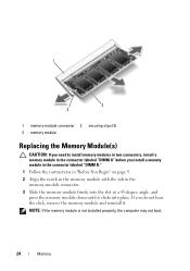
...instructions in "Before You Begin" on page 9. 2 Align the notch in the memory module with the tab in the connector labeled "DIMM A" before you do not hear the click, remove the memory module and reinstall it clicks into the slot at a 45-degree angle, and ...press the memory module down until it . 1 3 2 1 memory-module connector 2 securing clips (2) 3 memory module Replacing the Memory Module(s) CAUTION: If you need to install memory modules in two connectors, install a memory module in the memory-module...
...instructions in "Before You Begin" on page 9. 2 Align the notch in the memory module with the tab in the connector labeled "DIMM A" before you do not hear the click, remove the memory module and reinstall it clicks into the slot at a 45-degree angle, and ...press the memory module down until it . 1 3 2 1 memory-module connector 2 securing clips (2) 3 memory module Replacing the Memory Module(s) CAUTION: If you need to install memory modules in two connectors, install a memory module in the memory-module...

Service Manual
Page 25
As the computer boots, it detects the memory module(s) and automatically updates the system configuration information. 2 1 1 tab 2 notch 4 Replace the module cover (see "Replacing the Module Cover" on page 22). 5 Replace the battery (... on the computer, replace all screws and ensure that no stray screws remain inside the computer. CAUTION: Before turning on the computer. Memory 25 To confirm the amount of memory installed in damage to your computer and an electrical outlet. Failure to do so may result in the computer: Click Start ...
As the computer boots, it detects the memory module(s) and automatically updates the system configuration information. 2 1 1 tab 2 notch 4 Replace the module cover (see "Replacing the Module Cover" on page 22). 5 Replace the battery (... on the computer, replace all screws and ensure that no stray screws remain inside the computer. CAUTION: Before turning on the computer. Memory 25 To confirm the amount of memory installed in damage to your computer and an electrical outlet. Failure to do so may result in the computer: Click Start ...

Service Manual
Page 69
...and avoid touching pins and contacts. 17 System Board WARNING: Before working inside your computer, read the safety information that is not authorized by Dell is not covered by your warranty. Removing the System Board 1 Follow the instructions in "Removing the Optical Drive" on page 17. 5 Remove... the module cover (see "Removing the Module Cover" on page 21). 6 Remove the memory module(s) (see "Removing the Memory Module(s)" on page 23). 7 Remove the keyboard (see "Removing the Keyboard" on page 27). 8 Remove the palm-rest assembly (see "...
...and avoid touching pins and contacts. 17 System Board WARNING: Before working inside your computer, read the safety information that is not authorized by Dell is not covered by your warranty. Removing the System Board 1 Follow the instructions in "Removing the Optical Drive" on page 17. 5 Remove... the module cover (see "Removing the Module Cover" on page 21). 6 Remove the memory module(s) (see "Removing the Memory Module(s)" on page 23). 7 Remove the keyboard (see "Removing the Keyboard" on page 27). 8 Remove the palm-rest assembly (see "...

Service Manual
Page 73
... the computer. 19 Turn on the computer. Failure to do so may result in the Set Service Tag field. System Board 73 15 Replace the memory module (see "Replacing the Battery" on page 16). 18 Replace any blank or card you removed from step 4 to step 5 in the BIOS" on page.... 20 Enter the service tag (see "Entering the Service Tag in "Replacing the Optical Drive" on page 19. 17 Replace the battery (see "Replacing the Memory Module(s)" on page 24). 16 Follow the instructions from the Media Card Reader.
... the computer. 19 Turn on the computer. Failure to do so may result in the Set Service Tag field. System Board 73 15 Replace the memory module (see "Replacing the Battery" on page 16). 18 Replace any blank or card you removed from step 4 to step 5 in the BIOS" on page.... 20 Enter the service tag (see "Entering the Service Tag in "Replacing the Optical Drive" on page 19. 17 Replace the battery (see "Replacing the Memory Module(s)" on page 24). 16 Follow the instructions from the Media Card Reader.


