

Hardware Installation Guide
Page 9
.../Off Switch Warning C-24 Chassis Warning-Rack-Mounting and Servicing C-25 Reinforced Insulation Warning C-29 LAN Connections Only Warning C-30 No Field-Replaceable Units Warning C-31 Installation Warning C-32 SELV Source Warning C-33 Restricted Access Warning C-34 Shielded Ethernet Cables Warning... C-35 Grounded Equipment Warning C-36 Ground Connection Warning C-37 Qualified Personnel Warning C-38 DC Power Disconnection Warning C-39 Exposed Wire Lead Warning C-41 Contents 78-6461-04 Catalyst 2900 Series XL Hardware Installation ...
.../Off Switch Warning C-24 Chassis Warning-Rack-Mounting and Servicing C-25 Reinforced Insulation Warning C-29 LAN Connections Only Warning C-30 No Field-Replaceable Units Warning C-31 Installation Warning C-32 SELV Source Warning C-33 Restricted Access Warning C-34 Shielded Ethernet Cables Warning... C-35 Grounded Equipment Warning C-36 Ground Connection Warning C-37 Qualified Personnel Warning C-38 DC Power Disconnection Warning C-39 Exposed Wire Lead Warning C-41 Contents 78-6461-04 Catalyst 2900 Series XL Hardware Installation ...

Hardware Installation Guide
Page 11
... Guide documents the hardware features of the switches, explains how to identify and resolve some of Ethernet and local area networking. It describes the physical and performance characteristics of Catalyst 2900 series XL switches. Organization This guide is for the networking or computer technician responsible for installing a switch in a rack, on a desk, or on a wall...
... Guide documents the hardware features of the switches, explains how to identify and resolve some of Ethernet and local area networking. It describes the physical and performance characteristics of Catalyst 2900 series XL switches. Organization This guide is for the networking or computer technician responsible for installing a switch in a rack, on a desk, or on a wall...

Hardware Installation Guide
Page 21
... forwards the packet to the destination port 78-6461-04 Catalyst 2900 Series XL Hardware Installation Guide 1-1 The switches can connect workstations, Cisco IP Phones, and other network devices such as servers, routers, and other network devices. The 2900 XL LRE switches employ Long-Reach Ethernet (LRE), a very-high-data-rate digital subscriber line (VDSL...
... forwards the packet to the destination port 78-6461-04 Catalyst 2900 Series XL Hardware Installation Guide 1-1 The switches can connect workstations, Cisco IP Phones, and other network devices such as servers, routers, and other network devices. The 2900 XL LRE switches employ Long-Reach Ethernet (LRE), a very-high-data-rate digital subscriber line (VDSL...

Hardware Installation Guide
Page 22
...1 Product Overview • On the Catalyst 2924M XL, Catalyst 2912MF XL, and Catalyst 2924M XL DC switches, two module slots for 10BASE-T/100BASE-TX, 1000BASE-X, 1000BASE-T, Gigabit Ethernet, and asynchronous transfer mode (ATM) modules • On the Catalyst 2924M XL DC switch, a direct current (DC) power ...converter • On the Catalyst 2912 LRE XL and 2924 LRE XL switches, up to 24 LRE ports through one RJ-21 connector and hot swapping capability with the Cisco...
...1 Product Overview • On the Catalyst 2924M XL, Catalyst 2912MF XL, and Catalyst 2924M XL DC switches, two module slots for 10BASE-T/100BASE-TX, 1000BASE-X, 1000BASE-T, Gigabit Ethernet, and asynchronous transfer mode (ATM) modules • On the Catalyst 2924M XL DC switch, a direct current (DC) power ...converter • On the Catalyst 2912 LRE XL and 2924 LRE XL switches, up to 24 LRE ports through one RJ-21 connector and hot swapping capability with the Cisco...

Hardware Installation Guide
Page 24
... network topologies to gather link information and to display switch images to twenty-four Long-Reach Ethernet ports (See Figure 1-4). For more information about CMS, the CLI, and SNMP refer to support desktop-switching features. Catalyst 2900 Series XL Hardware Installation Guide 1-4 78-6461-04 All switches have up to twenty-four 10/100 ports...
... network topologies to gather link information and to display switch images to twenty-four Long-Reach Ethernet ports (See Figure 1-4). For more information about CMS, the CLI, and SNMP refer to support desktop-switching features. Catalyst 2900 Series XL Hardware Installation Guide 1-4 78-6461-04 All switches have up to twenty-four 10/100 ports...

Hardware Installation Guide
Page 27
...-optic cabling. Long-Reach Ethernet Ports The Long-Reach Ethernet (LRE) ports (Figure 1-4) use one RJ-21 connector to connect up to 24 Cisco LRE customer premises equipment (CPE) devices though structured or unstructured wiring, such as follows: • If the switch port and the port on...public system telephone network 78-6461-04 Catalyst 2900 Series XL Hardware Installation Guide 1-7 The PBX routes voice traffic to the switch and private branch exchange (PBX) switch or Public-Switched Telephone Network (PSTN). You can connect Cisco 575 LRE CPE and Cisco 585 LRE CPE devices to LRE ports...
...-optic cabling. Long-Reach Ethernet Ports The Long-Reach Ethernet (LRE) ports (Figure 1-4) use one RJ-21 connector to connect up to 24 Cisco LRE customer premises equipment (CPE) devices though structured or unstructured wiring, such as follows: • If the switch port and the port on...public system telephone network 78-6461-04 Catalyst 2900 Series XL Hardware Installation Guide 1-7 The PBX routes voice traffic to the switch and private branch exchange (PBX) switch or Public-Switched Telephone Network (PSTN). You can connect Cisco 575 LRE CPE and Cisco 585 LRE CPE devices to LRE ports...

Hardware Installation Guide
Page 28
...Table 1-1 Expansion Modules Module Type 10/100 Ethernet 100 BASE-FX Model Number WS-X2914-XL WS-X2914-XL-V WS-X2922-XL WS-X2922-XL-V WS-X2924-XL-V Catalyst 2900 Series XL Hardware Installation Guide 1-8 78-6461-04 For more information about the Cisco LRE 48 POTS Splitter (PS-1M-LRE-... above 700 kHz do not work when sharing a line with analog, Integrated Services Digital Network (ISDN), and digital private branch exchange (PBX) switch telephones that use frequencies above 700 kHz. [CSCdu73260] If the installation does not have a PBX, a homologated POTS splitter is not needed, and the...
...Table 1-1 Expansion Modules Module Type 10/100 Ethernet 100 BASE-FX Model Number WS-X2914-XL WS-X2914-XL-V WS-X2922-XL WS-X2922-XL-V WS-X2924-XL-V Catalyst 2900 Series XL Hardware Installation Guide 1-8 78-6461-04 For more information about the Cisco LRE 48 POTS Splitter (PS-1M-LRE-... above 700 kHz do not work when sharing a line with analog, Integrated Services Digital Network (ISDN), and digital private branch exchange (PBX) switch telephones that use frequencies above 700 kHz. [CSCdu73260] If the installation does not have a PBX, a homologated POTS splitter is not needed, and the...

Hardware Installation Guide
Page 29
...port mode changes the information provided by restarting that you use the switch LEDs to monitor switch activity and its performance. You can use to the Release Notes for Catalyst 2900 series XL switches. These modules automatically configure themselves when you install one of the ... If you insert them in a 2924M XL or Catalyst 2912MF XL switch (both supporting 8192 MAC addresses), the module fails POST. For a complete list and the minimum software release required, refer to select a port mode. The Ethernet Gigabit module supports several Gigabit Interface Converter (GBIC) ...
...port mode changes the information provided by restarting that you use the switch LEDs to monitor switch activity and its performance. You can use to the Release Notes for Catalyst 2900 series XL switches. These modules automatically configure themselves when you install one of the ... If you insert them in a 2924M XL or Catalyst 2912MF XL switch (both supporting 8192 MAC addresses), the module fails POST. For a complete list and the minimum software release required, refer to select a port mode. The Ethernet Gigabit module supports several Gigabit Interface Converter (GBIC) ...

Hardware Installation Guide
Page 35
...status Port duplex mode Port speed Description Long-Reach Ethernet (LRE) link status of the 10/100 or 100BASE-FX switch ports or the Ethernet link status on these switches only. The default setting is auto. 78-6461-04 Catalyst 2900 Series XL Hardware Installation Guide 1-15 Default... mode on the Catalyst 2912 LRE XL and Catalyst 2924 LRE XL switches. Note When the LRE mode...
...status Port duplex mode Port speed Description Long-Reach Ethernet (LRE) link status of the 10/100 or 100BASE-FX switch ports or the Ethernet link status on these switches only. The default setting is auto. 78-6461-04 Catalyst 2900 Series XL Hardware Installation Guide 1-15 Default... mode on the Catalyst 2912 LRE XL and Catalyst 2924 LRE XL switches. Note When the LRE mode...
Hardware Installation Guide
Page 37
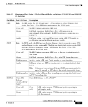
... mode. STAT Note In STAT mode, the LRE ports reflect the Ethernet link between the remote CPE and an Ethernet device such as STP checks the switch for possible loops. Cyan (off ) LRE port or remote CPE Ethernet port is administratively shut down . Blinking green Activity on the LRE ... Front-Panel Description Table 1-7 Meanings of Port Status LEDs for Different Modes on the LRE port. DUPLX Blinking amber Cisco IOS Release 12.0(5.x)WC1/ WC21 Activity on Catalyst 2912 LRE XL and 2924 LRE XL Switches Port Mode Port LED Color Description LRE Note In LRE mode, the 10/100...
... mode. STAT Note In STAT mode, the LRE ports reflect the Ethernet link between the remote CPE and an Ethernet device such as STP checks the switch for possible loops. Cyan (off ) LRE port or remote CPE Ethernet port is administratively shut down . Blinking green Activity on the LRE ... Front-Panel Description Table 1-7 Meanings of Port Status LEDs for Different Modes on the LRE port. DUPLX Blinking amber Cisco IOS Release 12.0(5.x)WC1/ WC21 Activity on Catalyst 2912 LRE XL and 2924 LRE XL Switches Port Mode Port LED Color Description LRE Note In LRE mode, the 10/100...

Hardware Installation Guide
Page 38
...information about the connected Cisco 575 LRE CPE devices. To verify the LRE CPE Ethernet link status from a switch with Cisco IOS Release 12.0(5.x)WC1 or Cisco IOS Release 12.0(5.x)WC2 provide information about any connected LRE CPE devices. The LEDs on Catalyst 2900 LRE XL switches with this release or... LEDs for Different Modes on Catalyst 2912 LRE XL and 2924 LRE XL Switches (continued) Port Mode SPEED Port LED Color Cisco IOS Release 12.0(5.x)WC1/ WC21 Description Cisco IOS Release 12.0(5.x)WC42 3 Cyan (off) Cyan (off) LRE port or remote CPE Ethernet port is operating at 10 Mbps...
...information about the connected Cisco 575 LRE CPE devices. To verify the LRE CPE Ethernet link status from a switch with Cisco IOS Release 12.0(5.x)WC1 or Cisco IOS Release 12.0(5.x)WC2 provide information about any connected LRE CPE devices. The LEDs on Catalyst 2900 LRE XL switches with this release or... LEDs for Different Modes on Catalyst 2912 LRE XL and 2924 LRE XL Switches (continued) Port Mode SPEED Port LED Color Cisco IOS Release 12.0(5.x)WC1/ WC21 Description Cisco IOS Release 12.0(5.x)WC42 3 Cyan (off) Cyan (off) LRE port or remote CPE Ethernet port is operating at 10 Mbps...

Hardware Installation Guide
Page 51
...switch and through the vents is unrestricted. • Temperature around it might be easily read. - Rear-panel power connector is within reach of the expansion modules, refer to the modules documentation in the Related Publications, page xv. • Clearance to Find the Catalyst 2900 XL and Catalyst 3500 XL Documentation flyer • Cisco...176;F (45°C). Chapter 2 Installation Preparing for Installation • For Long-Reach Ethernet (LRE) ports, cable lengths from the switch to the connected Ethernet device are up to 4921 feet (1500 meters). • Cabling is away from the...
...switch and through the vents is unrestricted. • Temperature around it might be easily read. - Rear-panel power connector is within reach of the expansion modules, refer to the modules documentation in the Related Publications, page xv. • Clearance to Find the Catalyst 2900 XL and Catalyst 3500 XL Documentation flyer • Cisco...176;F (45°C). Chapter 2 Installation Preparing for Installation • For Long-Reach Ethernet (LRE) ports, cable lengths from the switch to the connected Ethernet device are up to 4921 feet (1500 meters). • Cabling is away from the...

Hardware Installation Guide
Page 79
...B +- Terminal block plug Tie wrap Connecting to a 10/100 Port The switch 10/100 ports configure themselves to an RJ-45 connector on the front panel ... to workstations, servers, routers, and Cisco IP Phones, connect a straight-through Category 5 cable to operate at the speed of the connection. Pinouts for configuring the 10/100 Ethernet ports: • Let the ports autonegotiate... both speed and duplex. • Set the port speed and duplex parameters on page B-4. 78-6461-04 Catalyst 2900 Series XL Hardware ...
...B +- Terminal block plug Tie wrap Connecting to a 10/100 Port The switch 10/100 ports configure themselves to an RJ-45 connector on the front panel ... to workstations, servers, routers, and Cisco IP Phones, connect a straight-through Category 5 cable to operate at the speed of the connection. Pinouts for configuring the 10/100 Ethernet ports: • Let the ports autonegotiate... both speed and duplex. • Set the port speed and duplex parameters on page B-4. 78-6461-04 Catalyst 2900 Series XL Hardware ...
Hardware Installation Guide
Page 90
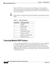
... Switch LED 1 2 3 4 5 6 7 8 Component Tested DRAM Flash memory Switch CPU System board CPU interface ASIC Switch core ASIC Ethernet controller ASIC Ethernet interfaces Correcting Module POST Failures If you install modules WS-X2914-XL or WS-X2922-XL in a Catalyst 2924M XL or Catalyst 2912MF XL switch,... port status LED associated with the module installed. Catalyst 2900 Series XL Hardware Installation Guide 3-2 78-6461-04 After the restart, the address capacity of the switch is operational. Call Cisco Systems if your switch does not pass POST. Understanding POST Results Chapter...
... Switch LED 1 2 3 4 5 6 7 8 Component Tested DRAM Flash memory Switch CPU System board CPU interface ASIC Switch core ASIC Ethernet controller ASIC Ethernet interfaces Correcting Module POST Failures If you install modules WS-X2914-XL or WS-X2922-XL in a Catalyst 2924M XL or Catalyst 2912MF XL switch,... port status LED associated with the module installed. Catalyst 2900 Series XL Hardware Installation Guide 3-2 78-6461-04 After the restart, the address capacity of the switch is operational. Call Cisco Systems if your switch does not pass POST. Understanding POST Results Chapter...

Hardware Installation Guide
Page 105
...Connectors and Cable Specifications This appendix describes the Catalyst 2900 XL switch ports and the cables and adapters that a straight-through cable and an adapter can be attached to other devices. Figure B-1 shows the pinouts. 78-6461-04 Catalyst 2900 Series XL Hardware Installation Guide B-1 These ...ports have their transmit (TD) and receive (RD) signals internally crossed so that you use standard RJ-45 connectors and Ethernet pinouts with internal crossovers, as shown by an ...
...Connectors and Cable Specifications This appendix describes the Catalyst 2900 XL switch ports and the cables and adapters that a straight-through cable and an adapter can be attached to other devices. Figure B-1 shows the pinouts. 78-6461-04 Catalyst 2900 Series XL Hardware Installation Guide B-1 These ...ports have their transmit (TD) and receive (RD) signals internally crossed so that you use standard RJ-45 connectors and Ethernet pinouts with internal crossovers, as shown by an ...

Hardware Installation Guide
Page 5
... 3-16 Where to Go Next 3-18 Troubleshooting 4-1 Diagnosing Problems 4-1 Verify Switch POST Results 4-2 Monitor Switch LEDs 4-2 Verify Switch Connections 4-2 Bad or Damaged Cable 4-2 Ethernet and Fiber Cables 4-3 Link Status 4-3 Transceiver Module Port Issues 4-3 Port and... the Switch IP Address and Configuration 4-5 Locating the Switch Serial Number 4-6 Technical Specifications A-1 Connector and Cable Specifications B-1 Connector Specifications B-1 10/100/1000 Ports B-1 Connecting to 1000BASE-T Devices B-2 SFP Module Ports B-3 Dual-Purpose Ports B-3 Catalyst 2960 Switch Hardware Installation...
... 3-16 Where to Go Next 3-18 Troubleshooting 4-1 Diagnosing Problems 4-1 Verify Switch POST Results 4-2 Monitor Switch LEDs 4-2 Verify Switch Connections 4-2 Bad or Damaged Cable 4-2 Ethernet and Fiber Cables 4-3 Link Status 4-3 Transceiver Module Port Issues 4-3 Port and... the Switch IP Address and Configuration 4-5 Locating the Switch Serial Number 4-6 Technical Specifications A-1 Connector and Cable Specifications B-1 Connector Specifications B-1 10/100/1000 Ports B-1 Connecting to 1000BASE-T Devices B-2 SFP Module Ports B-3 Dual-Purpose Ports B-3 Catalyst 2960 Switch Hardware Installation...

Hardware Installation Guide
Page 11
... Access Points, Cisco IP Phones, and other network devices including servers, routers, and other network devices. Table 1-1 describes the switch model features. Product Overview 1 C H A P T E R The Catalyst 2960 switch-also referred to as the switch-is an Ethernet switch to which you can deploy these switches outside of the Catalyst 2960 switch. Table 1-1 Catalyst 2960 Switch Model Descriptions Switch Model Catalyst 2960-8TC-S Catalyst 2960-24-S Catalyst 2960-24TC-S Catalyst 2960-48TC-S Catalyst 2960-48TT-S Catalyst 2960-48PST-S Catalyst 2960-24PC-S Supported...
... Access Points, Cisco IP Phones, and other network devices including servers, routers, and other network devices. Table 1-1 describes the switch model features. Product Overview 1 C H A P T E R The Catalyst 2960 switch-also referred to as the switch-is an Ethernet switch to which you can deploy these switches outside of the Catalyst 2960 switch. Table 1-1 Catalyst 2960 Switch Model Descriptions Switch Model Catalyst 2960-8TC-S Catalyst 2960-24-S Catalyst 2960-24TC-S Catalyst 2960-48TC-S Catalyst 2960-48TT-S Catalyst 2960-48PST-S Catalyst 2960-24PC-S Supported...

Hardware Installation Guide
Page 22
... access points that case, the PoE port becomes the backup power source for Cisco IP Phones and Cisco Aironet Access Points. • Each of the PoE ports on the Catalyst 2960 switches deliver up to 8 of the 10/100 ports on Power over Ethernet (PoE) circuits if interconnections are made aware of approximately 370-W PoE power...
... access points that case, the PoE port becomes the backup power source for Cisco IP Phones and Cisco Aironet Access Points. • Each of the PoE ports on the Catalyst 2960 switches deliver up to 8 of the 10/100 ports on Power over Ethernet (PoE) circuits if interconnections are made aware of approximately 370-W PoE power...

Hardware Installation Guide
Page 23
...Ethernet switch that first links up. This external power adapter (PWR-A=) is considered as an SFP module port. These Catalyst 2960 switches do not have an SFP module slot: • Catalyst 2960PD-8TT-L • Catalyst 2960-24LT-L • Catalyst 2960-24-S • Catalyst 2960-24TT-L • Catalyst 2960-48TT-L • Catalyst 2960-... about cabling requirements, see your SFP module documentation or the release notes for your Cisco representative. (See Figure 1-22.) OL-7075-09 Catalyst 2960 Switch Hardware Installation Guide 1-13 Each uplink port has two LEDs: one shows the status...
...Ethernet switch that first links up. This external power adapter (PWR-A=) is considered as an SFP module port. These Catalyst 2960 switches do not have an SFP module slot: • Catalyst 2960PD-8TT-L • Catalyst 2960-24LT-L • Catalyst 2960-24-S • Catalyst 2960-24TT-L • Catalyst 2960-48TT-L • Catalyst 2960-... about cabling requirements, see your SFP module documentation or the release notes for your Cisco representative. (See Figure 1-22.) OL-7075-09 Catalyst 2960 Switch Hardware Installation Guide 1-13 Each uplink port has two LEDs: one shows the status...

Hardware Installation Guide
Page 36
... Particulate Matter Cisco Ethernet switches are equipped with local and national electrical codes. A restricted access area can be accessed only through the use both GLC-GE-100XX and GLC-FE-100XX SFP modules. Statement 1074 Guidelines for Installation Chapter 2 Switch Installation (24... inside the chassis, which lists the cable specifications for 1000BASE-X and 100BASE-X SFP modules for the Catalyst 2960-8TC-L, 2960-8TC-S, 2960G-8TC-L, and 2960PD-8TT-L switches. You must be made using uninsulated exposed metal contacts, conductors, or terminals. Avoid using such interconnection...
... Particulate Matter Cisco Ethernet switches are equipped with local and national electrical codes. A restricted access area can be accessed only through the use both GLC-GE-100XX and GLC-FE-100XX SFP modules. Statement 1074 Guidelines for Installation Chapter 2 Switch Installation (24... inside the chassis, which lists the cable specifications for 1000BASE-X and 100BASE-X SFP modules for the Catalyst 2960-8TC-L, 2960-8TC-S, 2960G-8TC-L, and 2960PD-8TT-L switches. You must be made using uninsulated exposed metal contacts, conductors, or terminals. Avoid using such interconnection...


