
Hardware Installation Guide
Page 36
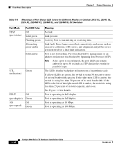
...Spanning Tree Protocol (STP). Port is operating in half duplex. The LEDs display backplane utilization on Catalyst 2912 XL, 2924C XL, 2924 XL, 2924MF XL, 2924M XL, and 2924M XL DC Switches Port Mode STAT (port status) Port LED Color Off Solid green Flashing green Alternating green-amber ...Figure 1-8 for possible loops. Port is operating in full duplex. If all port LEDs are monitored for Different Modes on a logarithmic scale. If the right-most LED is amber, the switch is using less than 25 percent of Port Status LED Colors for a link-fault indication. Port is using...
...Spanning Tree Protocol (STP). Port is operating in half duplex. The LEDs display backplane utilization on Catalyst 2912 XL, 2924C XL, 2924 XL, 2924MF XL, 2924M XL, and 2924M XL DC Switches Port Mode STAT (port status) Port LED Color Off Solid green Flashing green Alternating green-amber ...Figure 1-8 for possible loops. Port is operating in full duplex. If all port LEDs are monitored for Different Modes on a logarithmic scale. If the right-most LED is amber, the switch is using less than 25 percent of Port Status LED Colors for a link-fault indication. Port is using...
Hardware Installation Guide
Page 37
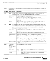
...LRE port is in a non-STP forwarding state or is in full-duplex mode. 78-6461-04 Catalyst 2900 Series XL Hardware Installation Guide 1-17 The Ethernet link default settings on the LRE ports are different from those on the LRE CPE unable to 30 seconds as a PC. See Table 1-5 for ...forwarding state. Port is sending or receiving data, but it is operating in STP forwarding state. Cisco IOS Release 12.0(5.x)WC42 3 Cyan (off) Cyan (off ) No LRE link present on Catalyst 2912 LRE XL and 2924 LRE XL Switches Port Mode Port LED Color Description LRE Note In LRE mode, the 10/100...
...LRE port is in a non-STP forwarding state or is in full-duplex mode. 78-6461-04 Catalyst 2900 Series XL Hardware Installation Guide 1-17 The Ethernet link default settings on the LRE ports are different from those on the LRE CPE unable to 30 seconds as a PC. See Table 1-5 for ...forwarding state. Port is sending or receiving data, but it is operating in STP forwarding state. Cisco IOS Release 12.0(5.x)WC42 3 Cyan (off) Cyan (off ) No LRE link present on Catalyst 2912 LRE XL and 2924 LRE XL Switches Port Mode Port LED Color Description LRE Note In LRE mode, the 10/100...

Hardware Installation Guide
Page 38
...-04 Front-Panel Description Chapter 1 Product Overview Table 1-7 Meanings of Port Status LEDs for Different Modes on Catalyst 2912 LRE XL and 2924 LRE XL Switches (continued) Port Mode SPEED Port LED Color Cisco IOS Release 12.0(5.x)WC1/ WC21 Description Cisco IOS Release 12.0(5.x)WC42 3 Cyan (off) Cyan (off) LRE port or remote CPE Ethernet...
...-04 Front-Panel Description Chapter 1 Product Overview Table 1-7 Meanings of Port Status LEDs for Different Modes on Catalyst 2912 LRE XL and 2924 LRE XL Switches (continued) Port Mode SPEED Port LED Color Cisco IOS Release 12.0(5.x)WC1/ WC21 Description Cisco IOS Release 12.0(5.x)WC42 3 Cyan (off) Cyan (off) LRE port or remote CPE Ethernet...
Hardware Installation Guide
Page 47
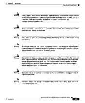
... 2 Installation Preparing for Installation Warning This product relies on the phase conductors (all national laws and regulations. 78-6461-04 Catalyst 2900 Series XL Hardware Installation Guide 2-3 Warning Care must be given to connecting units to that the host is not overloaded....present within the power supply even when the power switch is off and the power cord is used on the building's installation for short-circuit (overcurrent) protection. Ensure that receptacle. Warning Do not work on the label is different from the power outlet voltage, do not connect the...
... 2 Installation Preparing for Installation Warning This product relies on the phase conductors (all national laws and regulations. 78-6461-04 Catalyst 2900 Series XL Hardware Installation Guide 2-3 Warning Care must be given to connecting units to that the host is not overloaded....present within the power supply even when the power switch is off and the power cord is used on the building's installation for short-circuit (overcurrent) protection. Ensure that receptacle. Warning Do not work on the label is different from the power outlet voltage, do not connect the...

Hardware Installation Guide
Page 2
... of California, Berkeley (UCB) as part of UCB's public domain version of a program developed by different circuit breakers or fuses.) Modifications to operate the product. If it may cause harmful interference to correct ...CISCO AND THE ABOVE-NAMED SUPPLIERS DISCLAIM ALL WARRANTIES, EXPRESSED OR IMPLIED, INCLUDING, WITHOUT LIMITATION, THOSE OF MERCHANTABILITY, FITNESS FOR A PARTICULAR PURPOSE AND NONINFRINGEMENT OR ARISING FROM A COURSE OF DEALING, USAGE, OR TRADE PRACTICE. Any examples, command display output, and figures included in a residential installation. Catalyst 2960 Switch...
... of California, Berkeley (UCB) as part of UCB's public domain version of a program developed by different circuit breakers or fuses.) Modifications to operate the product. If it may cause harmful interference to correct ...CISCO AND THE ABOVE-NAMED SUPPLIERS DISCLAIM ALL WARRANTIES, EXPRESSED OR IMPLIED, INCLUDING, WITHOUT LIMITATION, THOSE OF MERCHANTABILITY, FITNESS FOR A PARTICULAR PURPOSE AND NONINFRINGEMENT OR ARISING FROM A COURSE OF DEALING, USAGE, OR TRADE PRACTICE. Any examples, command display output, and figures included in a residential installation. Catalyst 2960 Switch...

Hardware Installation Guide
Page 27
... Link fault. Blinking green Port is not sending or receiving packets. Note When installed in Catalyst 2960 switches, 1000BASE-T SFP modules can operate at 10, 100, or 1000 Mb/s in Different Modes on the port LEDs. Table 1-6 explains how to Catalyst 2960 switches that support PoE. Blinking green Activity. Blinking amber Port is blocked by Spanning Tree...
... Link fault. Blinking green Port is not sending or receiving packets. Note When installed in Catalyst 2960 switches, 1000BASE-T SFP modules can operate at 10, 100, or 1000 Mb/s in Different Modes on the port LEDs. Table 1-6 explains how to Catalyst 2960 switches that support PoE. Blinking green Activity. Blinking amber Port is blocked by Spanning Tree...
Hardware Installation Guide
Page 28
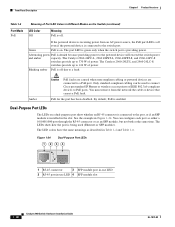
... is being used to connect Cisco prestandard IP Phones or wireless access points or IEEE 802.3af-compliant devices to 370 W of power. The LEDs show whether an RJ-45 connector is connected to 124 W of power. The Catalyst 2960-24LT-L and 2960-24LC-S switches provide up to PoE ports.... LED Colors in Different Modes on the Switch (continued) LED Color Off Meaning PoE is off even if the powered device is connected to a PoE port. The port LED is green only when the switch port is providing power. The Catalyst 2960-24PC-L, 2960 48PST-L, 2960-48PST-S, and 2960-24PC-S switches provide up to...
... is being used to connect Cisco prestandard IP Phones or wireless access points or IEEE 802.3af-compliant devices to 370 W of power. The LEDs show whether an RJ-45 connector is connected to 124 W of power. The Catalyst 2960-24LT-L and 2960-24LC-S switches provide up to PoE ports.... LED Colors in Different Modes on the Switch (continued) LED Color Off Meaning PoE is off even if the powered device is connected to a PoE port. The port LED is green only when the switch port is providing power. The Catalyst 2960-24PC-L, 2960 48PST-L, 2960-48PST-S, and 2960-24PC-S switches provide up to...

Hardware Installation Guide
Page 58
... the specifications in the left and right side panels. For information applicable to the other devices that is a different part than the Catalyst 2960-8TC-L and Catalyst 2960G-8TC-L switches. You can use to avoid overloading the receiver. Make sure the cabling is less than 15.43 miles ... this equipment to install the switch: • Number-2 Phillips screwdriver • Drill with its front panel facing up or sideways. When you use these conditions - and 48-Port Switches)." To order a cable guard, contact your Cisco representative and use shorter lengths ...
... the specifications in the left and right side panels. For information applicable to the other devices that is a different part than the Catalyst 2960-8TC-L and Catalyst 2960G-8TC-L switches. You can use to avoid overloading the receiver. Make sure the cabling is less than 15.43 miles ... this equipment to install the switch: • Number-2 Phillips screwdriver • Drill with its front panel facing up or sideways. When you use these conditions - and 48-Port Switches)." To order a cable guard, contact your Cisco representative and use shorter lengths ...
Hardware Installation Guide
Page 77
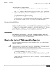
..., or alignment errors, verify that the cable distance from the manufacturer. The switch LEDs begin blinking after an additional 8 seconds, and then the switch reboots. OL-7075-09 Catalyst 2960 Switch Hardware Installation Guide 4-5 It is common for cabling guidelines. Caution This procedure ...if the connected port does not autonegotiate. Chapter 4 Troubleshooting Clearing the Switch IP Address and Configuration These circumstances can result in a mismatch: • A manually set speed or duplex parameter is different from the manually set speed or duplex parameter on the connected port....
..., or alignment errors, verify that the cable distance from the manufacturer. The switch LEDs begin blinking after an additional 8 seconds, and then the switch reboots. OL-7075-09 Catalyst 2960 Switch Hardware Installation Guide 4-5 It is common for cabling guidelines. Caution This procedure ...if the connected port does not autonegotiate. Chapter 4 Troubleshooting Clearing the Switch IP Address and Configuration These circumstances can result in a mismatch: • A manually set speed or duplex parameter is different from the manually set speed or duplex parameter on the connected port....

Hardware Installation Guide
Page 93
... pin on the inside of the cable. Pin 1 200915 OL-7075-09 Catalyst 2960 Switch Hardware Installation Guide B-7 Hold the cable ends side-by-side, with the tab at the back. Appendix B Connector and Cable Specifications Cable and Adapter Specifications Figure B-8 Switch 1 TP0+ 2 TP03 TP1+ 6 TP1- 4 TP2+ 5 TP27 TP3+ 8 TP3- 65274 ... the right plug. (See Figure B-9.) Figure B-9 Pin 1 Identifying a Crossover Cable Pin 1 on one connector and pin 1 on the other connector should be a different color from the wire connected to identify a crossover cable and also describes the adapter pinouts.
... pin on the inside of the cable. Pin 1 200915 OL-7075-09 Catalyst 2960 Switch Hardware Installation Guide B-7 Hold the cable ends side-by-side, with the tab at the back. Appendix B Connector and Cable Specifications Cable and Adapter Specifications Figure B-8 Switch 1 TP0+ 2 TP03 TP1+ 6 TP1- 4 TP2+ 5 TP27 TP3+ 8 TP3- 65274 ... the right plug. (See Figure B-9.) Figure B-9 Pin 1 Identifying a Crossover Cable Pin 1 on one connector and pin 1 on the other connector should be a different color from the wire connected to identify a crossover cable and also describes the adapter pinouts.


