

Hardware Installation Guide
Page 2
... in a particular installation. and Aironet, ASIST, BPX, Catalyst, CCDA, CCDP, CCIE, CCNA, CCNP, Cisco, the Cisco Certified Internetwork Expert logo, Cisco IOS, the Cisco IOS logo, Cisco Press, Cisco Systems, Cisco Systems Capital, the Cisco Systems logo, Empowering the Internet Generation, Enterprise/Solver, EtherChannel...is , make certain the equipment and the television or radio are registered trademarks of Cisco Systems, Inc.; These specifications are trademarks of the FCC rules. CISCO AND THE ABOVE-NAMED SUPPLIERS DISCLAIM ALL WARRANTIES, EXPRESSED OR IMPLIED, INCLUDING, WITHOUT...
... in a particular installation. and Aironet, ASIST, BPX, Catalyst, CCDA, CCDP, CCIE, CCNA, CCNP, Cisco, the Cisco Certified Internetwork Expert logo, Cisco IOS, the Cisco IOS logo, Cisco Press, Cisco Systems, Cisco Systems Capital, the Cisco Systems logo, Empowering the Internet Generation, Enterprise/Solver, EtherChannel...is , make certain the equipment and the television or radio are registered trademarks of Cisco Systems, Inc.; These specifications are trademarks of the FCC rules. CISCO AND THE ABOVE-NAMED SUPPLIERS DISCLAIM ALL WARRANTIES, EXPRESSED OR IMPLIED, INCLUDING, WITHOUT...

Hardware Installation Guide
Page 7
... 2-19 Installing the Switch on a Wall 2-20 Attaching the Brackets to the Switch 2-21 Mounting the Switch to a Wall 2-22 Powering On the Switch and Running POST 2-24 Connecting to DC Power 2-25 Preparing for Installation 2-25 Grounding the Switch 2-26 Wiring the... Go Next 2-43 Troubleshooting 3-1 Understanding POST Results 3-1 Correcting Module POST Failures 3-2 Diagnosing Problems 3-3 Technical Specifications A-1 Connectors and Cable Specifications B-1 Connector Specifications B-1 10/100 Ports B-1 100BASE-FX Ports B-2 Contents 78-6461-04 Catalyst 2900 Series XL Hardware Installation Guide vii
... 2-19 Installing the Switch on a Wall 2-20 Attaching the Brackets to the Switch 2-21 Mounting the Switch to a Wall 2-22 Powering On the Switch and Running POST 2-24 Connecting to DC Power 2-25 Preparing for Installation 2-25 Grounding the Switch 2-26 Wiring the... Go Next 2-43 Troubleshooting 3-1 Understanding POST Results 3-1 Correcting Module POST Failures 3-2 Diagnosing Problems 3-3 Technical Specifications A-1 Connectors and Cable Specifications B-1 Connector Specifications B-1 10/100 Ports B-1 100BASE-FX Ports B-2 Contents 78-6461-04 Catalyst 2900 Series XL Hardware Installation Guide vii

Hardware Installation Guide
Page 8
... Ports B-3 Console Port B-3 Cable and Adapter Specifications B-4 Crossover and Straight-Through Cable Pinouts B-4 RJ-21 Cable Pinouts B-5 Console Port B-5 Identifying a Rollover Cable B-6 Connecting to a PC B-6 Connecting to a Terminal B-7 Translated Safety Warnings C-1 Attaching the Cisco RPS (model PWR600-AC-RPS) C-1 Attaching the Cisco RPS (model PWR300-AC-RPS-N1) C-2 Qualified... C-14 Supply Circuit Warning C-15 Voltage Warning C-16 Power Supply Warning C-17 Lightning Activity Warning C-19 Product Disposal Warning C-21 Catalyst 2900 Series XL Hardware Installation Guide viii 78-6461-04
... Ports B-3 Console Port B-3 Cable and Adapter Specifications B-4 Crossover and Straight-Through Cable Pinouts B-4 RJ-21 Cable Pinouts B-5 Console Port B-5 Identifying a Rollover Cable B-6 Connecting to a PC B-6 Connecting to a Terminal B-7 Translated Safety Warnings C-1 Attaching the Cisco RPS (model PWR600-AC-RPS) C-1 Attaching the Cisco RPS (model PWR300-AC-RPS-N1) C-2 Qualified... C-14 Supply Circuit Warning C-15 Voltage Warning C-16 Power Supply Warning C-17 Lightning Activity Warning C-19 Product Disposal Warning C-21 Catalyst 2900 Series XL Hardware Installation Guide viii 78-6461-04

Hardware Installation Guide
Page 11
.... Chapter 3, "Troubleshooting," describes how to install a switch, and provides troubleshooting information and specifications. It describes the physical and performance characteristics of the switches, explains how to identify and resolve some of the problems that you are familiar with the concepts and terminology of Catalyst 2900 series XL switches. Preface Audience This guide is organized into...
.... Chapter 3, "Troubleshooting," describes how to install a switch, and provides troubleshooting information and specifications. It describes the physical and performance characteristics of the switches, explains how to identify and resolve some of the problems that you are familiar with the concepts and terminology of Catalyst 2900 series XL switches. Preface Audience This guide is organized into...

Hardware Installation Guide
Page 12
... used to connect to convey instructions and information: Command descriptions use the following conventions to the switch. Catalyst 2900 Series XL Hardware Installation Guide xii 78-6461-04 Conventions Preface Appendix A, "Technical Specifications," lists the physical and environmental specifications for which you supply values are in italic. In this situation, you enter is in...
... used to connect to convey instructions and information: Command descriptions use the following conventions to the switch. Catalyst 2900 Series XL Hardware Installation Guide xii 78-6461-04 Conventions Preface Appendix A, "Technical Specifications," lists the physical and environmental specifications for which you supply values are in italic. In this situation, you enter is in...

Hardware Installation Guide
Page 18
... streamline business processes and improve productivity. Obtaining Technical Assistance Cisco provides Cisco.com as a starting point for this platform, click Give Us Your Feedback. If you are using the product-specific CD and you can find information about Cisco and our networking solutions, xviii Catalyst 2900 Series XL Hardware Installation Guide 78-6461-04 Otherwise...
... streamline business processes and improve productivity. Obtaining Technical Assistance Cisco provides Cisco.com as a starting point for this platform, click Give Us Your Feedback. If you are using the product-specific CD and you can find information about Cisco and our networking solutions, xviii Catalyst 2900 Series XL Hardware Installation Guide 78-6461-04 Otherwise...
Hardware Installation Guide
Page 19
... order products, check on the status of the above cases, use the Cisco TAC website to quickly find answers to their relationships with Cisco. In each of an order, access technical support, and view benefits specific to your questions. Network functionality is noticeably impaired, but most business operations ... is available to the TAC website: http://www.cisco.com/tac P3 and P4 level problems are also available. To register for Cisco.com, go to the following website: http://www.cisco.com/register/ 78-6461-04 Catalyst 2900 Series XL Hardware Installation Guide xix Customers and...
... order products, check on the status of the above cases, use the Cisco TAC website to quickly find answers to their relationships with Cisco. In each of an order, access technical support, and view benefits specific to your questions. Network functionality is noticeably impaired, but most business operations ... is available to the TAC website: http://www.cisco.com/tac P3 and P4 level problems are also available. To register for Cisco.com, go to the following website: http://www.cisco.com/register/ 78-6461-04 Catalyst 2900 Series XL Hardware Installation Guide xix Customers and...

Hardware Installation Guide
Page 24
... configure and monitor a standalone switch, a specific cluster member, or an entire switch cluster. You can manage switch configuration settings, performance, security, and collect statistics by using Telnet from a remote management station. • Simple network management protocol (SNMP)-SNMP provides a means to modify switch- You can manage the switch from the CLI. Catalyst 2900 Series XL Hardware Installation...
... configure and monitor a standalone switch, a specific cluster member, or an entire switch cluster. You can manage switch configuration settings, performance, security, and collect statistics by using Telnet from a remote management station. • Simple network management protocol (SNMP)-SNMP provides a means to modify switch- You can manage the switch from the CLI. Catalyst 2900 Series XL Hardware Installation...

Hardware Installation Guide
Page 26
... XL Hardware Installation Guide 1-6 78-6461-04 When connecting the switch to workstations, servers, routers, and Cisco IP Phones, be explicitly set to operate in Appendix B, "Connectors and Cable Specifications." For more information about these features. Refer to the Catalyst 2900 Series XL and Catalyst 3500 Series XL Software Configuration Guide for more info on...
... XL Hardware Installation Guide 1-6 78-6461-04 When connecting the switch to workstations, servers, routers, and Cisco IP Phones, be explicitly set to operate in Appendix B, "Connectors and Cable Specifications." For more information about these features. Refer to the Catalyst 2900 Series XL and Catalyst 3500 Series XL Software Configuration Guide for more info on...

Hardware Installation Guide
Page 33
... providing power to another device (redundancy has been allocated to the appropriate switch documentation for redundant power system (RPS) descriptions specific for the switch. For more information see the "Cisco RPS Connector" section on the Catalyst 2912 XL, 2924C XL, 2924 XL, 2924MF XL, 2924M XL, and... 2924M XL DC Switches Color Off Green Blinking green Amber RPS Status RPS is not installed...
... providing power to another device (redundancy has been allocated to the appropriate switch documentation for redundant power system (RPS) descriptions specific for the switch. For more information see the "Cisco RPS Connector" section on the Catalyst 2912 XL, 2924C XL, 2924 XL, 2924MF XL, 2924M XL, and... 2924M XL DC Switches Color Off Green Blinking green Amber RPS Status RPS is not installed...

Hardware Installation Guide
Page 42
...-6461-04 Warning Attach only the Cisco RPS (model PWR600-AC-RPS) to the RPS 600 receptacle. Cisco RPS Connector Specific Cisco RPS models support specific Catalyst 2900 XL switches: • Cisco RPS 600 (model PWR600-AC-RPS)-supports the Catalyst 2912 XL, 2924C XL, 2924 XL, 2924MF XL, and 2924M XL switches. • Cisco RPS 300 (model PWR300-AC-RPS...
...-6461-04 Warning Attach only the Cisco RPS (model PWR600-AC-RPS) to the RPS 600 receptacle. Cisco RPS Connector Specific Cisco RPS models support specific Catalyst 2900 XL switches: • Cisco RPS 600 (model PWR600-AC-RPS)-supports the Catalyst 2912 XL, 2924C XL, 2924 XL, 2924MF XL, and 2924M XL switches. • Cisco RPS 300 (model PWR300-AC-RPS...

Hardware Installation Guide
Page 51
... these items: • Where to Find the Catalyst 2900 XL and Catalyst 3500 XL Documentation flyer • Cisco Documentation CD-ROM • AC power cord 78-6461-04 Catalyst 2900 Series XL Hardware Installation Guide 2-7 Note If the switch is installed in Appendix A, "Technical Specifications." • Airflow around the switch and through the vents is unrestricted. •...
... these items: • Where to Find the Catalyst 2900 XL and Catalyst 3500 XL Documentation flyer • Cisco Documentation CD-ROM • AC power cord 78-6461-04 Catalyst 2900 Series XL Hardware Installation Guide 2-7 Note If the switch is installed in Appendix A, "Technical Specifications." • Airflow around the switch and through the vents is unrestricted. •...

Hardware Installation Guide
Page 79
... 10BASE-T and 100BASE-TX devices: Step 1 When connecting to workstations, servers, routers, and Cisco IP Phones, connect a straight-through Category 5 cable to operate at the speed of the...for the cables are described in no linkage. Chapter 2 Installation Figure 2-27 Inserting Terminal Block Into Switch Connecting to switches or repeaters, use a crossover Category 5 cable. B +- When connecting to a 10/100 ... "Cable and Adapter Specifications" section on both speed and duplex. • Set the port speed and duplex parameters on page B-4. 78-6461-04 Catalyst 2900 Series XL Hardware...
... 10BASE-T and 100BASE-TX devices: Step 1 When connecting to workstations, servers, routers, and Cisco IP Phones, connect a straight-through Category 5 cable to operate at the speed of the...for the cables are described in no linkage. Chapter 2 Installation Figure 2-27 Inserting Terminal Block Into Switch Connecting to switches or repeaters, use a crossover Category 5 cable. B +- When connecting to a 10/100 ... "Cable and Adapter Specifications" section on both speed and duplex. • Set the port speed and duplex parameters on page B-4. 78-6461-04 Catalyst 2900 Series XL Hardware...

Hardware Installation Guide
Page 86
...accessed the switch, you want to connect the switch console port to the Catalyst 2900 Series XL Modules Installation Guide and the Catalyst 2900 Series XL ATM Modules Installation and Configuration Guide. For console port and adapter pinout information, see the "Cable and Adapter Specifications" section... you can order a kit (part number ACS-DSBUASYN=) containing that adapter from Cisco. See the Catalyst 2900 Series XL and Catalyst 3500 Series XL Software Configuration Guide for instructions. 2-42 Catalyst 2900 Series XL Hardware Installation Guide 78-6461-04 Connecting to a Module Port ...
...accessed the switch, you want to connect the switch console port to the Catalyst 2900 Series XL Modules Installation Guide and the Catalyst 2900 Series XL ATM Modules Installation and Configuration Guide. For console port and adapter pinout information, see the "Cable and Adapter Specifications" section... you can order a kit (part number ACS-DSBUASYN=) containing that adapter from Cisco. See the Catalyst 2900 Series XL and Catalyst 3500 Series XL Software Configuration Guide for instructions. 2-42 Catalyst 2900 Series XL Hardware Installation Guide 78-6461-04 Connecting to a Module Port ...

Hardware Installation Guide
Page 99
Table A-6 lists the agency approvals for additional specifications. For switches that support modules (Catalyst 2912MF XL and 2924M XL), also refer to the Catalyst 2900 Series XL Modules Installation Guide and the Catalyst 2900 Series XL ATM Modules Installation Guide for EMI and safety. 78-6461-04 Catalyst 2900 Series XL Hardware Installation Guide A-1 A A P P E N D I X Technical Specifications Table A-1, Table A-2, Table A-3, and Table A-5 list the technical specifications for the Catalyst 2900 series switches.
Table A-6 lists the agency approvals for additional specifications. For switches that support modules (Catalyst 2912MF XL and 2924M XL), also refer to the Catalyst 2900 Series XL Modules Installation Guide and the Catalyst 2900 Series XL ATM Modules Installation Guide for EMI and safety. 78-6461-04 Catalyst 2900 Series XL Hardware Installation Guide A-1 A A P P E N D I X Technical Specifications Table A-1, Table A-2, Table A-3, and Table A-5 list the technical specifications for the Catalyst 2900 series switches.
Hardware Installation Guide
Page 100
Appendix A Technical Specifications Table A-1 Technical Specifications for the Catalyst 2912 XL and Catalyst 2912MF XL Switches Environmental Ranges Operating temperature Storage temperature Operating humidity Operating altitude Storage altitude Power Requirements AC input voltage DC input voltages Catalyst 2912 XL 32 to 113°F (0 to 45°C) -4 ...(maximum) 239 Btus per hour 7 lb (3.2 kg) Dimensions (H x W x D) 1.73 x 17.5 x 9.79 in. (4.4 x 44.5 x 24.8 cm) Catalyst 2912MF XL 32 to 113°F (0 to 45°C) -4 to 149°F (-10 to 65°C) 10 to 85% (noncondensing) Up to 10,000 ft...
Appendix A Technical Specifications Table A-1 Technical Specifications for the Catalyst 2912 XL and Catalyst 2912MF XL Switches Environmental Ranges Operating temperature Storage temperature Operating humidity Operating altitude Storage altitude Power Requirements AC input voltage DC input voltages Catalyst 2912 XL 32 to 113°F (0 to 45°C) -4 ...(maximum) 239 Btus per hour 7 lb (3.2 kg) Dimensions (H x W x D) 1.73 x 17.5 x 9.79 in. (4.4 x 44.5 x 24.8 cm) Catalyst 2912MF XL 32 to 113°F (0 to 45°C) -4 to 149°F (-10 to 65°C) 10 to 85% (noncondensing) Up to 10,000 ft...

Hardware Installation Guide
Page 101
nm = nanometers 2. Transmit - 1. dBm = decibel milliwatt Catalyst 2924C XL 32 to 113°F (0 to 45°C) -4 to 149°F (-10 to 65°C) 10 to 85% (noncondensing) ... 9.79 in . (4.4 x 44.5 x 24.8 cm) Optical transmitter - wavelength Optical sensibility of the - receiver Optical power transmitter - Appendix A Technical Specifications Table A-2 Technical Specifications for the Catalyst 2924 XL and Catalyst 2924C XL Switches Catalyst 2924 XL Environmental Operating Ranges Operating temperature 32 to 113°F (0 to 45°C) Storage temperature -4 to 149°F (-10 to...
nm = nanometers 2. Transmit - 1. dBm = decibel milliwatt Catalyst 2924C XL 32 to 113°F (0 to 45°C) -4 to 149°F (-10 to 65°C) 10 to 85% (noncondensing) ... 9.79 in . (4.4 x 44.5 x 24.8 cm) Optical transmitter - wavelength Optical sensibility of the - receiver Optical power transmitter - Appendix A Technical Specifications Table A-2 Technical Specifications for the Catalyst 2924 XL and Catalyst 2924C XL Switches Catalyst 2924 XL Environmental Operating Ranges Operating temperature 32 to 113°F (0 to 45°C) Storage temperature -4 to 149°F (-10 to...
Hardware Installation Guide
Page 102
Appendix A Technical Specifications Table A-3 Technical Specifications for the Catalyst 2924M XL Switches Environmental Operating Ranges Operating temperature 32 to 113°F (0 to 45°C) Storage temperature -4 to 149°F (-10 to 65°C) Operating humidity 10 to ... Btus per hour Physical Dimensions Weight 13.5 lb (6.12 kg) 15 lb (6.8 kg) with two modules installed Dimensions (H x W x D) 3.46 x 17.5 x 12 in. (8.8 x 44.5 x 30.5 cm) Catalyst 2900 Series XL Hardware Installation Guide A-4 78-6461-04
Appendix A Technical Specifications Table A-3 Technical Specifications for the Catalyst 2924M XL Switches Environmental Operating Ranges Operating temperature 32 to 113°F (0 to 45°C) Storage temperature -4 to 149°F (-10 to 65°C) Operating humidity 10 to ... Btus per hour Physical Dimensions Weight 13.5 lb (6.12 kg) 15 lb (6.8 kg) with two modules installed Dimensions (H x W x D) 3.46 x 17.5 x 12 in. (8.8 x 44.5 x 30.5 cm) Catalyst 2900 Series XL Hardware Installation Guide A-4 78-6461-04
Hardware Installation Guide
Page 103
...,000 ft (3000 m) Up to 15,000 ft (4570 m) 100W -36 to 15,000 ft (4570 m) Catalyst 2900 Series XL Hardware Installation Guide A-5 Appendix A Technical Specifications 78-6461-04 Table A-4 Technical Specifications for Catalyst 2924M XL DC Switches Environmental Ranges Operating temperature Storage temperature Operating humidity Operating altitude Storage altitude Power Requirements Power consumption DC...
...,000 ft (3000 m) Up to 15,000 ft (4570 m) 100W -36 to 15,000 ft (4570 m) Catalyst 2900 Series XL Hardware Installation Guide A-5 Appendix A Technical Specifications 78-6461-04 Table A-4 Technical Specifications for Catalyst 2924M XL DC Switches Environmental Ranges Operating temperature Storage temperature Operating humidity Operating altitude Storage altitude Power Requirements Power consumption DC...
Hardware Installation Guide
Page 104
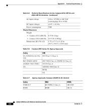
... A Technical Specifications Table A-5 Technical Specifications for the Catalyst 2912 LRE XL and 2924 LRE XL Switches (continued) AC input voltage 100 to 127/200 to 240 VAC (autoranging) 50 to 60 Hz DC input voltages +12V @12A Power consumption 70W Physical Dimensions Weight • Catalyst 2912 LRE XL 8.75 lb (4 kg) • Catalyst 2924 LRE XL..., TS001 CE EMI FCC Part 15 Class A EN 55022 Class A (CISPR 22 Class A) VCCI Class A AS/NZS 3548 Class A BCIQ CE Table A-7 Agency Approvals (Catalyst 2924M XL DC Switch) Safety NOM 019 BSMI EMC EN 50082-1 Class A BSMI NEBS GR-1089 GR-63...
... A Technical Specifications Table A-5 Technical Specifications for the Catalyst 2912 LRE XL and 2924 LRE XL Switches (continued) AC input voltage 100 to 127/200 to 240 VAC (autoranging) 50 to 60 Hz DC input voltages +12V @12A Power consumption 70W Physical Dimensions Weight • Catalyst 2912 LRE XL 8.75 lb (4 kg) • Catalyst 2924 LRE XL..., TS001 CE EMI FCC Part 15 Class A EN 55022 Class A (CISPR 22 Class A) VCCI Class A AS/NZS 3548 Class A BCIQ CE Table A-7 Agency Approvals (Catalyst 2924M XL DC Switch) Safety NOM 019 BSMI EMC EN 50082-1 Class A BSMI NEBS GR-1089 GR-63...