

Hardware Installation Guide
Page 5
... Documentation Feedback xviii Obtaining Technical Assistance xviii Cisco.com xviii Technical Assistance Center xix Contacting TAC by Using the Cisco TAC Website xix Contacting TAC by Telephone xx Product Overview 1-1 Features 1-1 Management Interface Options 1-4 Front-Panel Description 1-4 10/100 Ports 1-6 100BASE-FX Ports 1-7 Long-Reach Ethernet Ports 1-7 Catalyst 2900 Series XL Hardware Installation Guide v
... Documentation Feedback xviii Obtaining Technical Assistance xviii Cisco.com xviii Technical Assistance Center xix Contacting TAC by Using the Cisco TAC Website xix Contacting TAC by Telephone xx Product Overview 1-1 Features 1-1 Management Interface Options 1-4 Front-Panel Description 1-4 10/100 Ports 1-6 100BASE-FX Ports 1-7 Long-Reach Ethernet Ports 1-7 Catalyst 2900 Series XL Hardware Installation Guide v

Hardware Installation Guide
Page 6
...14 Module Slot LEDs 1-19 Rear-Panel Description 1-19 Power Connectors 1-21 Internal Power Supply Connector 1-21 DC Power Connector 1-21 Cisco RPS Connector 1-22 Console Port 1-23 ...2 C H A P T E R Installation 2-1 Preparing for Installation 2-1 Warnings 2-1 EMC Regulatory Statements 2-4 U.S.A. 2-4 Taiwan 2-4 Japan 2-5 Korea 2-5 Hungary 2-6 Installation Guidelines 2-6 Verifying Package Contents 2-7 Installing the Switch on a Table or Shelf 2-9 Installing the Switch in a Rack 2-9 Removing Screws from the Switch 2-11 Attaching the Brackets to a Catalyst...
...14 Module Slot LEDs 1-19 Rear-Panel Description 1-19 Power Connectors 1-21 Internal Power Supply Connector 1-21 DC Power Connector 1-21 Cisco RPS Connector 1-22 Console Port 1-23 ...2 C H A P T E R Installation 2-1 Preparing for Installation 2-1 Warnings 2-1 EMC Regulatory Statements 2-4 U.S.A. 2-4 Taiwan 2-4 Japan 2-5 Korea 2-5 Hungary 2-6 Installation Guidelines 2-6 Verifying Package Contents 2-7 Installing the Switch on a Table or Shelf 2-9 Installing the Switch in a Rack 2-9 Removing Screws from the Switch 2-11 Attaching the Brackets to a Catalyst...

Hardware Installation Guide
Page 12
...are in boldface. • Arguments for the switches and the regulatory agency approvals. Caution Means reader be used to connect to the switch. Catalyst 2900 Series XL Hardware Installation Guide xii 78-...6461-04 Conventions This guide uses the following conventions to materials not contained in this manual. Appendix C, "Translated Safety Warnings," provides translations in various languages of data. Notes contain helpful suggestions or references to convey instructions and information: Command descriptions...
...are in boldface. • Arguments for the switches and the regulatory agency approvals. Caution Means reader be used to connect to the switch. Catalyst 2900 Series XL Hardware Installation Guide xii 78-...6461-04 Conventions This guide uses the following conventions to materials not contained in this manual. Appendix C, "Translated Safety Warnings," provides translations in various languages of data. Notes contain helpful suggestions or references to convey instructions and information: Command descriptions...

Hardware Installation Guide
Page 21
...)-based technology that describe the Catalyst 2900 series XL switches, hereafter referred to as the switches. • Switch features, including management options • Descriptions of the front and rear panels • Descriptions of the LEDs Features The switches are stackable 10/100 Ethernet switches to 4921 feet (1500 meters). The switches can connect workstations, Cisco IP Phones, and other network...
...)-based technology that describe the Catalyst 2900 series XL switches, hereafter referred to as the switches. • Switch features, including management options • Descriptions of the front and rear panels • Descriptions of the LEDs Features The switches are stackable 10/100 Ethernet switches to 4921 feet (1500 meters). The switches can connect workstations, Cisco IP Phones, and other network...

Hardware Installation Guide
Page 23
Chapter 1 Product Overview Figure 1-1 Catalyst 2900 Series XL Switches Version Number Description WS-C2912-LRE-XL 4 fixed autosensing 10/100 ports INPUT OUTPUT PWR PWR RESET TEMP FAN 9X 10X 11X 12X 12 LRE ports Cisco RPS 300 WS-C2924-LRE-XL 4 fixed autosensing 10/100 ports 24 LRE ports INPUT OUTPUT PWR PWR RESET...
Chapter 1 Product Overview Figure 1-1 Catalyst 2900 Series XL Switches Version Number Description WS-C2912-LRE-XL 4 fixed autosensing 10/100 ports INPUT OUTPUT PWR PWR RESET TEMP FAN 9X 10X 11X 12X 12 LRE ports Cisco RPS 300 WS-C2924-LRE-XL 4 fixed autosensing 10/100 ports 24 LRE ports INPUT OUTPUT PWR PWR RESET...

Hardware Installation Guide
Page 24
... 1-3), two module slots (see Figure 1-3), and up to twenty-four Long-Reach Ethernet ports (See Figure 1-4). Front-Panel Description Depending on the switch. Using CMS, you can be launched from anywhere in your management station directly to the...OpenView. You can fully configure and monitor the switch and switch cluster members from a remote management station. • Simple network management protocol (SNMP)-SNMP provides a means to the Catalyst 2900 Series XL and Catalyst 3500 Series XL Software Configuration Guide. Catalyst 2900 Series XL Hardware Installation Guide 1-4 78-...
... 1-3), two module slots (see Figure 1-3), and up to twenty-four Long-Reach Ethernet ports (See Figure 1-4). Front-Panel Description Depending on the switch. Using CMS, you can be launched from anywhere in your management station directly to the...OpenView. You can fully configure and monitor the switch and switch cluster members from a remote management station. • Simple network management protocol (SNMP)-SNMP provides a means to the Catalyst 2900 Series XL and Catalyst 3500 Series XL Software Configuration Guide. Catalyst 2900 Series XL Hardware Installation Guide 1-4 78-...
Hardware Installation Guide
Page 25
52646 Chapter 1 Product Overview Figure 1-2 Catalyst 2900 XL Front-Panel 10/100 Ports Front-Panel Description MODE 1X 2X 3X 4X 5X 6X 7X 8X 9X 10X 10BASE-T/100BA1S0E0-BTaXseFX 11X 12X 13X 14X 15X 16X 17X 18X 19X 20X 21X ...22X Catalyst10209B0AS0ES-FEXRIES XL 23 24 10/100 ports 100BASE-FX ports Figure 1-3 Catalyst 2900 XL 100BASE-FX ports and...
52646 Chapter 1 Product Overview Figure 1-2 Catalyst 2900 XL Front-Panel 10/100 Ports Front-Panel Description MODE 1X 2X 3X 4X 5X 6X 7X 8X 9X 10X 10BASE-T/100BA1S0E0-BTaXseFX 11X 12X 13X 14X 15X 16X 17X 18X 19X 20X 21X ...22X Catalyst10209B0AS0ES-FEXRIES XL 23 24 10/100 ports 100BASE-FX ports Figure 1-3 Catalyst 2900 XL 100BASE-FX ports and...

Hardware Installation Guide
Page 26
... connected to an AC power source. For more info on the Catalyst 2900 XL switches provide protocol support for more information about these features. Front-Panel Description Chapter 1 Product Overview 10/100 Ports The 10/100 switch ports (see Figure 1-2 and Figure 1-4) can connect to any... combination of the attached device and advertises its own capabilities. Cisco IP Phones-connected to the Catalyst 2900 Series XL and Catalyst 3500 Series XL...
... connected to an AC power source. For more info on the Catalyst 2900 XL switches provide protocol support for more information about these features. Front-Panel Description Chapter 1 Product Overview 10/100 Ports The 10/100 switch ports (see Figure 1-2 and Figure 1-4) can connect to any... combination of the attached device and advertises its own capabilities. Cisco IP Phones-connected to the Catalyst 2900 Series XL and Catalyst 3500 Series XL...

Hardware Installation Guide
Page 27
...configuring the LRE ports, refer to the switch and private branch exchange (PBX) switch or Public-Switched Telephone Network (PSTN). For information about the Cisco LRE CPE devices, refer to the patch panel through a private branch exchange (PBX) switch, a Cisco LRE 48 POTS Splitter can be used. ...78-6461-04 Catalyst 2900 Series XL Hardware Installation Guide 1-7 Chapter 1 Product Overview Front-Panel Description 100BASE-FX Ports The 100BASE-FX ports use one RJ-21 connector to connect up to 6562 feet (2 kilometers). The connection distances between the LRE switch port and ...
...configuring the LRE ports, refer to the switch and private branch exchange (PBX) switch or Public-Switched Telephone Network (PSTN). For information about the Cisco LRE CPE devices, refer to the patch panel through a private branch exchange (PBX) switch, a Cisco LRE 48 POTS Splitter can be used. ...78-6461-04 Catalyst 2900 Series XL Hardware Installation Guide 1-7 Chapter 1 Product Overview Front-Panel Description 100BASE-FX Ports The 100BASE-FX ports use one RJ-21 connector to connect up to 6562 feet (2 kilometers). The connection distances between the LRE switch port and ...

Hardware Installation Guide
Page 28
Front-Panel Description Chapter 1 Product Overview (PSTN). Table 1-1 lists the modules that use frequencies above 700 kHz. [CSCdu73260] If the installation does not have a PBX, a homologated POTS splitter is required to directly connect to other switch ports and is not needed, and the switch can connect ...-X2922-XL WS-X2922-XL-V WS-X2924-XL-V Catalyst 2900 Series XL Hardware Installation Guide 1-8 78-6461-04 For more information about the Cisco LRE 48 POTS Splitter (PS-1M-LRE-48), refer to digital PBX switches that the module slots support. Digital telephones connected to...
Front-Panel Description Chapter 1 Product Overview (PSTN). Table 1-1 lists the modules that use frequencies above 700 kHz. [CSCdu73260] If the installation does not have a PBX, a homologated POTS splitter is required to directly connect to other switch ports and is not needed, and the switch can connect ...-X2922-XL WS-X2922-XL-V WS-X2924-XL-V Catalyst 2900 Series XL Hardware Installation Guide 1-8 78-6461-04 For more information about the Cisco LRE 48 POTS Splitter (PS-1M-LRE-48), refer to digital PBX switches that the module slots support. Digital telephones connected to...

Hardware Installation Guide
Page 29
...devices. If you install one of the LEDs and the Mode button that you insert them in a 2924M XL or Catalyst 2912MF XL switch (both supporting 8192 MAC addresses), the module fails POST. Changing a port mode changes the information provided by restarting that... restart, the switch address capacity is reduced to the Catalyst 2900 Series XL Modules Installation Guide and the Catalyst 2900 Series XL ATM Modules Installation and Configuration Guide for detailed information on self-test (POST) verifies that switch. Chapter 1 Product Overview Front-Panel Description Table 1-1 Expansion...
...devices. If you install one of the LEDs and the Mode button that you insert them in a 2924M XL or Catalyst 2912MF XL switch (both supporting 8192 MAC addresses), the module fails POST. Changing a port mode changes the information provided by restarting that... restart, the switch address capacity is reduced to the Catalyst 2900 Series XL Modules Installation Guide and the Catalyst 2900 Series XL ATM Modules Installation and Configuration Guide for detailed information on self-test (POST) verifies that switch. Chapter 1 Product Overview Front-Panel Description Table 1-1 Expansion...

Hardware Installation Guide
Page 30
... Series XL Hardware Installation Guide 78-6461-04 The Catalyst 2900 Series XL and Catalyst 3500 Series XL Software Configuration Guide describes how to use CMS to manage standalone or individual switches and how to use cluster management software to manage switch clusters]. Front-Panel Description Chapter 1 Product Overview All of the LEDs described in...
... Series XL Hardware Installation Guide 78-6461-04 The Catalyst 2900 Series XL and Catalyst 3500 Series XL Software Configuration Guide describes how to use CMS to manage standalone or individual switches and how to use cluster management software to manage switch clusters]. Front-Panel Description Chapter 1 Product Overview All of the LEDs described in...

Hardware Installation Guide
Page 31
Chapter 1 Product Overview Figure 1-6 Catalyst 2912MF XL, 2924M XL, and 2924M XL DC LEDs 10BASE-FX port LEDs Front-Panel Description 12 1 MODE 2 3 4 5 100BASE-FX 6 7 System LED RPS LED Expansion slot status LED Port mode LED Mode button 48003 78-6461-04 Catalyst 2900 Series XL Hardware Installation Guide 1-11
Chapter 1 Product Overview Figure 1-6 Catalyst 2912MF XL, 2924M XL, and 2924M XL DC LEDs 10BASE-FX port LEDs Front-Panel Description 12 1 MODE 2 3 4 5 100BASE-FX 6 7 System LED RPS LED Expansion slot status LED Port mode LED Mode button 48003 78-6461-04 Catalyst 2900 Series XL Hardware Installation Guide 1-11

Hardware Installation Guide
Page 32
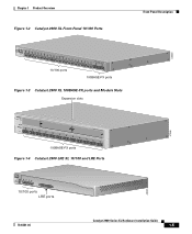
... the System LED colors during POST, see the "Powering On the Switch and Running POST" section on page 2-24. 1-12 Catalyst 2900 Series XL Hardware Installation Guide 78-6461-04 Table 1-2 lists the LED colors and their meanings. Front-Panel Description Figure 1-7 Catalyst 2912 LRE XL and 2924 LRE XL LEDs 10/100 port...
... the System LED colors during POST, see the "Powering On the Switch and Running POST" section on page 2-24. 1-12 Catalyst 2900 Series XL Hardware Installation Guide 78-6461-04 Table 1-2 lists the LED colors and their meanings. Front-Panel Description Figure 1-7 Catalyst 2912 LRE XL and 2924 LRE XL LEDs 10/100 port...

Hardware Installation Guide
Page 33
...installed. RPS is connected but is unavailable because it restarts. For more information see the "Cisco RPS Connector" section on the Catalyst 2912 LRE XL and 2924 LRE XL Switches Color Off Solid green Blinking green RPS Status RPS is operational. Pressing the Mode button on .... Refer to provide back-up . Chapter 1 Product Overview Front-Panel Description RPS LED The Catalyst 2912 LRE XL and Catalyst 2924 LRE XL switches use the Cisco RPS 600 (model PWR600-AC-RPS). All other Catalyst 2900 XL and Catalyst 3500 XL switches use the Cisco RPS 300 (model PWR300-AC-RPS-N1).
...installed. RPS is connected but is unavailable because it restarts. For more information see the "Cisco RPS Connector" section on the Catalyst 2912 LRE XL and 2924 LRE XL Switches Color Off Solid green Blinking green RPS Status RPS is operational. Pressing the Mode button on .... Refer to provide back-up . Chapter 1 Product Overview Front-Panel Description RPS LED The Catalyst 2912 LRE XL and Catalyst 2924 LRE XL switches use the Cisco RPS 600 (model PWR600-AC-RPS). All other Catalyst 2900 XL and Catalyst 3500 XL switches use the Cisco RPS 300 (model PWR300-AC-RPS-N1).

Hardware Installation Guide
Page 34
...Table 1-5) determine the type of the port LED colors also changes. This is in standby mode or in a fault condition. Contact Cisco Systems. The internal power supply in use by the switch. (See Figure 1-8.) The port duplex mode: full duplex or half duplex, and default modes: • 10/100 ports: auto... this device). Press the Standby/Active button on the Catalyst 2912 XL, 2924C XL, 2924 XL, 2924MF XL, 2924M XL, and 2924M XL DC Switches Mode LED STAT UTL FDUP 100 Port Mode Port status Switch utilization Port duplex mode Port speed Description The port status. If it does not, the RPS...
...Table 1-5) determine the type of the port LED colors also changes. This is in standby mode or in a fault condition. Contact Cisco Systems. The internal power supply in use by the switch. (See Figure 1-8.) The port duplex mode: full duplex or half duplex, and default modes: • 10/100 ports: auto... this device). Press the Standby/Active button on the Catalyst 2912 XL, 2924C XL, 2924 XL, 2924MF XL, 2924M XL, and 2924M XL DC Switches Mode LED STAT UTL FDUP 100 Port Mode Port status Switch utilization Port duplex mode Port speed Description The port status. If it does not, the RPS...

Hardware Installation Guide
Page 35
... the LRE mode is active, the 10/100 switch ports on the Catalyst 2912 LRE XL and Catalyst 2924 LRE XL switches. The default setting is auto. 78-6461-04 Catalyst 2900 Series XL Hardware Installation Guide 1-15 Chapter 1 Product Overview Front-Panel Description Table 1-5 Port Mode LEDs on Catalyst 2912 LRE XL and 2924 LRE XL...
... the LRE mode is active, the 10/100 switch ports on the Catalyst 2912 LRE XL and Catalyst 2924 LRE XL switches. The default setting is auto. 78-6461-04 Catalyst 2900 Series XL Hardware Installation Guide 1-15 Chapter 1 Product Overview Front-Panel Description Table 1-5 Port Mode LEDs on Catalyst 2912 LRE XL and 2924 LRE XL...
Hardware Installation Guide
Page 36
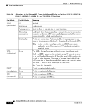
...Port is operating at 10 Mbps. Port is transmitting or receiving data. If the right-most LED is amber, the switch is operating at 100 Mbps. 1-16 Catalyst 2900 Series XL Hardware Installation Guide 78-6461-04 Port is not forwarding. Link fault. If all port LEDs are monitored... blocked by Spanning Tree Protocol (STP). Port is using 50 percent or more of its total bandwidth capacity. Link present. Activity. Front-Panel Description Chapter 1 Product Overview Table 1-6 Meanings of Port Status LED Colors for Different Modes on a logarithmic scale. If the LED to 30 seconds ...
...Port is operating at 10 Mbps. Port is transmitting or receiving data. If the right-most LED is amber, the switch is operating at 100 Mbps. 1-16 Catalyst 2900 Series XL Hardware Installation Guide 78-6461-04 Port is not forwarding. Link fault. If all port LEDs are monitored... blocked by Spanning Tree Protocol (STP). Port is using 50 percent or more of its total bandwidth capacity. Link present. Activity. Front-Panel Description Chapter 1 Product Overview Table 1-6 Meanings of Port Status LED Colors for Different Modes on a logarithmic scale. If the LED to 30 seconds ...
Hardware Installation Guide
Page 37
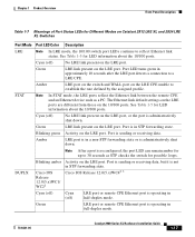
...to 30 seconds as a PC. Cisco IOS Release 12.0(5.x)WC42 3 Cyan (off) Cyan (off ) No LRE link present on Catalyst 2912 LRE XL and 2924 LRE XL Switches Port Mode Port LED Color Description LRE Note In LRE mode, the 10/100 switch port LEDs continue to establish the rate...-duplex mode. 78-6461-04 Catalyst 2900 Series XL Hardware Installation Guide 1-17 Port is operating in STP forwarding state. Note After a port is administratively shut down . Blinking green Activity on the LRE port. Chapter 1 Product Overview Front-Panel Description Table 1-7 Meanings of Port Status...
...to 30 seconds as a PC. Cisco IOS Release 12.0(5.x)WC42 3 Cyan (off) Cyan (off ) No LRE link present on Catalyst 2912 LRE XL and 2924 LRE XL Switches Port Mode Port LED Color Description LRE Note In LRE mode, the 10/100 switch port LEDs continue to establish the rate...-duplex mode. 78-6461-04 Catalyst 2900 Series XL Hardware Installation Guide 1-17 Port is operating in STP forwarding state. Note After a port is administratively shut down . Blinking green Activity on the LRE port. Chapter 1 Product Overview Front-Panel Description Table 1-7 Meanings of Port Status...

Hardware Installation Guide
Page 38
... 1 Product Overview Table 1-7 Meanings of Port Status LEDs for Different Modes on Catalyst 2912 LRE XL and 2924 LRE XL Switches (continued) Port Mode SPEED Port LED Color Cisco IOS Release 12.0(5.x)WC1/ WC21 Description Cisco IOS Release 12.0(5.x)WC42 3 Cyan (off) Cyan (off) LRE port or remote CPE Ethernet port is operating at 10...
... 1 Product Overview Table 1-7 Meanings of Port Status LEDs for Different Modes on Catalyst 2912 LRE XL and 2924 LRE XL Switches (continued) Port Mode SPEED Port LED Color Cisco IOS Release 12.0(5.x)WC1/ WC21 Description Cisco IOS Release 12.0(5.x)WC42 3 Cyan (off) Cyan (off) LRE port or remote CPE Ethernet port is operating at 10...