Cisco 2960-48TT - Catalyst Switch Support and Manuals
Get Help and Manuals for this Cisco item
View All Support Options Below
Free Cisco 2960-48TT manuals!
Problems with Cisco 2960-48TT?
Ask a Question
Free Cisco 2960-48TT manuals!
Problems with Cisco 2960-48TT?
Ask a Question
Popular Cisco 2960-48TT Manual Pages
Hardware Installation Guide - Page 7

...Module Port 2-42 Connecting to the Console Port 2-42 Where to Go Next 2-43
Troubleshooting 3-1 Understanding POST Results 3-1 Correcting Module POST Failures 3-2 Diagnosing Problems 3-3
Technical Specifications A-1
Connectors and Cable Specifications B-1 Connector Specifications B-1 10/100 Ports B-1 100BASE-FX Ports B-2
Contents
78-6461-04
Catalyst 2900 Series XL Hardware Installation Guide
vii
Hardware Installation Guide - Page 11

Organization
This guide is for the networking or computer technician responsible for installing a switch in a rack, on a desk, or on a wall. Chapter 3, "Troubleshooting," describes how to install a switch, and provides troubleshooting information and specifications. Chapter 2, "Installation," provides the procedures for installing and configuring a Catalyst 2900 series XL switch. It ...
Hardware Installation Guide - Page 16

... Note (not orderable but is available on Cisco.com)
• Catalyst GigaStack Gigabit Interface Converter Hardware Installation Guide (order number DOC-786460=)
• Cisco LRE CPE Hardware Installation Guide (order number DOC-7811469=)
• Installation Notes for the Cisco LRE 48 POTS Splitter (order number DOC-7812250=)
• Installation Notes for Wall-Mount Brackets (order number...
Hardware Installation Guide - Page 25
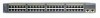
... Module Slots Expansion slots
47286
12
1
MODE
2 3
Catalyst 2900 SERIES XL
4 5
100BASE-FX
6
7
8
9
10
11
12
100BASE-FX ports
Figure 1-4 Catalyst 2900 LRE XL 10/100 and LRE Ports
INPUT OUTPUT
PWR PWR
RESET TEMP FAN
9X 10X 11X 12X
10/100 ports LRE ports
Catalyst 2900 LRE XL
48005
78-6461-04
Catalyst 2900 Series XL Hardware Installation Guide
1-5
Hardware Installation Guide - Page 26

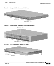
... set to operate in Appendix B, "Connectors and Cable Specifications." Unlike the 3524-PWR XL switch, the Catalyst 2900 XL switches do not provide inline power. Pinouts for 100BASE-TX traffic.
When connecting the switch to workstations, servers, routers, and Cisco IP Phones, be connected to an AC power source. If the connected device also supports autonegotiation, the switch port negotiates...
Hardware Installation Guide - Page 28

... 10/100 Ethernet
100 BASE-FX
Model Number WS-X2914-XL WS-X2914-XL-V WS-X2922-XL WS-X2922-XL-V WS-X2924-XL-V
Catalyst 2900 Series XL Hardware Installation Guide
1-8
78-6461-04 Digital telephones connected to digital PBX switches that use frequencies above 700 kHz do not work when sharing a line with analog, Integrated Services Digital Network (ISDN), and digital...
Hardware Installation Guide - Page 37
... a connection to reflect Ethernet link
status.
Amber
LRE port on the switch and WALL port on the LRE port. Port LED turns green in full-duplex mode.
78-6461-04
Catalyst 2900 Series XL Hardware Installation Guide
1-17
Green
LRE port or remote CPE Ethernet port is reconfigured, the port LED can remain amber for LED information about the 10/100...
Hardware Installation Guide - Page 53
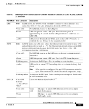
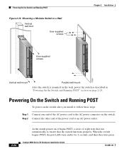
... the only unit in the rack.
• When mounting this unit in the rack.
Note Figure 2-1 shows brackets for one-rack-unit switches.
78-6461-04
Catalyst 2900 Series XL Hardware Installation Guide
2-9 Rack-mount points are provided to ensure your safety:
• This unit should be attached to a 19-, 23-, or 24-inch...
Hardware Installation Guide - Page 68
... on , it begins POST, a series of the power cord to an AC power outlet.
2-24
As the switch powers on the switch. Step 2 Connect the other end of eight tests that the switch functions properly. Catalyst 2900 Series XL Hardware Installation Guide
78-6461-04 When the switch begins POST, the port LEDs turn amber for 2 seconds, and then they turn...
Hardware Installation Guide - Page 79

...parameters manually set the speed and duplex parameters. When connecting to a 10/100 Port
74080
CONSOLE
BERFEOFREERPOCTOWONEMNRAENCUTAINL G
DC INPUT
ICNUPRURTE: 3N6T:-
72 4-2A
A +- Terminal block plug Tie wrap
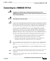
Connecting to a 10/100 Port
The switch 10/100 ports configure themselves to an RJ-45 connector on page B-4.
78-6461-04
Catalyst 2900 Series XL Hardware Installation Guide
2-35...
Hardware Installation Guide - Page 80

... about connecting devices to each 10/100 port.
2-36
Catalyst 2900 Series XL Hardware Installation Guide
78-6461-04
If the port LED does not turn on, the device at the other end of the cable to the switch. Connecting to a 10/100 Port
Figure 2-28 Connecting to a 10/100 Switch Port
Chapter 2 Installation
MODE
1X 2X 3X 4X 5X...
Hardware Installation Guide - Page 81
... 412 meters.
• If the switch port and the port on the attached device are configured for full-duplex operation, the connection can connect the 100BASE-FX ports to other 100BASE-FX-compatible network devices, such as shown in Figure 2-29.
78-6461-04
Catalyst 2900 Series XL Hardware Installation Guide
2-37 Connect one end of the...
Hardware Installation Guide - Page 99

... Table A-2, Table A-3, and Table A-5 list the technical specifications for additional specifications. For switches that support modules (Catalyst 2912MF XL and 2924M XL), also refer to the Catalyst 2900 Series XL Modules Installation Guide and the Catalyst 2900 Series XL ATM Modules Installation Guide for the Catalyst 2900 series switches. Table A-6 lists the agency approvals for EMI and safety...
Hardware Installation Guide - Page 105

..., as shown by an X in the port name.
Connector Specifications
10/100 Ports
The 10/100 Ethernet ports use to connect the switch to the port. Figure B-1 shows the pinouts.
78-6461-04
Catalyst 2900 Series XL Hardware Installation Guide
B-1 APPENDIX
B
Connectors and Cable Specifications
This appendix describes the Catalyst 2900 XL switch ports and the cables and adapters that a straight...
Hardware Installation Guide - Page 156
...-to-DB-25 terminal B-7 RJ-45-to-DB-9 terminal B-6 cable B-6 connecting to 2-42 to 2-43 default characteristics 2-42
conventions, document xii crossover cable
connectivity problems 3-5 pinout B-4
D
DC power connecting to 2-25 to 2-35 specifications A-5 warning C-29 to C-30, C-39
default characteristics of the console port 2-42
IN-2
Catalyst 2900 Series XL Hardware Installation Guide
78-6461-04
Cisco 2960-48TT Reviews
We have not received any reviews for Cisco yet.