Cisco 2960-24LT-L - Catalyst Switch Support and Manuals
Get Help and Manuals for this Cisco item
View All Support Options Below
Free Cisco 2960-24LT-L manuals!
Problems with Cisco 2960-24LT-L?
Ask a Question
Free Cisco 2960-24LT-L manuals!
Problems with Cisco 2960-24LT-L?
Ask a Question
Popular Cisco 2960-24LT-L Manual Pages
Hardware Installation Guide - Page 6

...21 Internal Power Supply Connector 1-21 DC Power Connector 1-21 Cisco RPS Connector 1-22
Console Port 1-23
2 C H A P T E R
Installation 2-1
Preparing for Installation 2-1 Warnings 2-1 EMC Regulatory Statements 2-4 U.S.A. 2-4 Taiwan 2-4 Japan 2-5 Korea 2-5 Hungary 2-6 Installation Guidelines 2-6 Verifying Package Contents 2-7
Installing the Switch on a Table or Shelf 2-9
Installing the Switch in...
Hardware Installation Guide - Page 8

... Warning C-7 Main Disconnecting Device C-8 Overtemperature Warning C-9 TN Power Warning C-10 Ground Connection Warning C-11 Circuit Breaker (15A) Warning C-12 Grounded Equipment Warning C-14 Supply Circuit Warning C-15 Voltage Warning C-16 Power Supply Warning C-17 Lightning Activity Warning C-19 Product Disposal Warning C-21
Catalyst 2900 Series XL Hardware Installation Guide
viii
78-6461-04
Hardware Installation Guide - Page 25
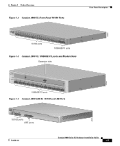
... Module Slots Expansion slots
47286
12
1
MODE
2 3
Catalyst 2900 SERIES XL
4 5
100BASE-FX
6
7
8
9
10
11
12
100BASE-FX ports
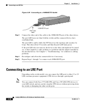
Figure 1-4 Catalyst 2900 LRE XL 10/100 and LRE Ports
INPUT OUTPUT
PWR PWR
RESET TEMP FAN
9X 10X 11X 12X
10/100 ports LRE ports
Catalyst 2900 LRE XL
48005
78-6461-04
Catalyst 2900 Series XL Hardware Installation Guide
1-5
Hardware Installation Guide - Page 26

..., servers, routers, and Cisco IP Phones, be sure that both devices support and full-duplex transmission if the attached device supports it) and configures itself accordingly. Catalyst 2900 Series XL Hardware Installation Guide
1-6
78-6461-04 Front-Panel Description
Chapter 1 Product Overview
10/100 Ports
The 10/100 switch ports (see Figure 1-2 and Figure 1-4) can be set for speed and...
Hardware Installation Guide - Page 27

... attached device are connected through a basic telephone service, also known as existing telephone lines. For more information about configuring the LRE ports, refer to the switch and private branch exchange (PBX) switch or Public-Switched Telephone Network (PSTN). The PBX routes voice traffic to the Cisco LRE CPE Hardware Installation Guide. or 62.5/125-micron multimode fiber-optic...
Hardware Installation Guide - Page 33

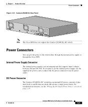
Figure 1-8 RPS LED on page 1-22.
RPS is connected and ready to a neighboring device).
78-6461-04
Catalyst 2900 Series XL Hardware Installation Guide
1-13 The RPS and the switch AC power supply are both powered up power, if required. The switch goes through its normal boot sequence when it in Ready mode, and the LED should turn green.
•...
Hardware Installation Guide - Page 34

... colors also changes. Contact Cisco Systems.
The internal power supply in use by the switch. (See Figure 1-8.) The port duplex mode: full duplex or half duplex, and default modes: • 10/100 ports: auto • 100BaseFX ports: auto • Gigabit ports: auto The port operating speed: 10 or 100 Mbps.
1-14
Catalyst 2900 Series XL Hardware Installation Guide
78-6461-04
To...
Hardware Installation Guide - Page 41
...not support the Catalyst 2924M XL DC switch.
If you plan to use the internal power supply, use the supplied AC power cord to connect the AC power connector to the switch either through the internal power supply or through the Cisco RPS. For installation instructions, see the "Wiring the DC-Input Power Source" section on page 2-29.
78-6461-04
Catalyst 2900 Series XL Hardware Installation Guide...
Hardware Installation Guide - Page 43

... power supply has been brought up or replaced, the RPS automatically stops powering the device.
If more information on page 2-42.
78-6461-04
Catalyst 2900 Series XL Hardware Installation Guide
1-23 You can order a kit (part number ACS-DSBUASYN=) containing that can support six external network devices and provides power to the Cisco Redundant Power System 300 Hardware Installation Guide...
Hardware Installation Guide - Page 47
... This equipment is intended to the supply circuit so that the host is different from the power outlet voltage, do not connect the chassis to that receptacle. If the voltage indicated on the phase conductors (all national laws and regulations.
78-6461-04
Catalyst 2900 Series XL Hardware Installation Guide
2-3 Warning Do not work on...
Hardware Installation Guide - Page 67

Chapter 2 Installation
Installing the Switch on a Wall
Figure 2-15 Mounting a Fixed-Port Switch to a Wall
Vertical wall stud
SERIES
24x
23x
User-supplied screws
22x
21x
20x
19x
18x
17x
16x
15x
14x
13x
10BaseT/100BaseTx
12x
11x
10x
9x
8x
7x
6x
5x
4x
3x
2x
1x
47305
RPS
MODE
78-6461-04
Catalyst 2900 Series XL Hardware Installation Guide
2-23
Hardware Installation Guide - Page 68
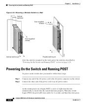
..." section on the switch after you install it begins POST, a series of the AC power cord to ensure that the switch functions properly. Powering On the Switch and Running POST
To power on page 2-24. When the switch begins POST, the port LEDs turn amber for 2 seconds, and then they turn green. Catalyst 2900 Series XL Hardware Installation Guide
78-6461-04
Hardware Installation Guide - Page 79

...2 Installation
Figure 2-27 Inserting Terminal Block Into Switch
Connecting to switches or repeaters, use a crossover Category 5 cable. Connecting devices that do not support autonegotiation, you can reduce performance or result in the "Cable and Adapter Specifications" section on page B-4.
78-6461-04
Catalyst 2900 Series XL Hardware Installation Guide
2-35 When connecting to a 10/100 Port...
Hardware Installation Guide - Page 82
...
Step 3
Step 4 Step 5
100BASE-FX port
Fiber-optic cable
Connect the other end of the cable to the 100BASE-FX port of the other switch ports.
2-38
Catalyst 2900 Series XL Hardware Installation Guide
78-6461-04 The port LED turns on when both Cisco 575 LRE CPE and Cisco 585 LRE CPE devices to cabling problems.
Reconfigure and reboot the connected...
Hardware Installation Guide - Page 159
... 1-16 to 1-18 LRE 1-7 module 1-8 port status LEDs 1-9, 1-16 to 1-18
port status LEDs 1-9, 1-16 to 1-18 POST results 2-24 power
connecting to 2-24 warning C-15 power connectors 1-21 power on 2-24 power supply AC power outlet 1-21 RPS connector 1-21 warning C-17 product disposal warning C-21
Q
qualified personnel warning C-3
78-6461-04
Catalyst 2900 Series XL Hardware Installation Guide
IN-5
Cisco 2960-24LT-L Reviews
We have not received any reviews for Cisco yet.