

Hardware Installation Guide
Page 42
... cable end) to connect four external devices to the four DC output power modules. Note Do not connect the switch power cord to the Cisco Redundant Power System Hardware Installation Guide. 1-22 Catalyst 2900 Series XL Hardware Installation Guide 78-6461-04 The switches do not recommend the redundant-with-reboot configuration. We do not support...
... cable end) to connect four external devices to the four DC output power modules. Note Do not connect the switch power cord to the Cisco Redundant Power System Hardware Installation Guide. 1-22 Catalyst 2900 Series XL Hardware Installation Guide 78-6461-04 The switches do not recommend the redundant-with-reboot configuration. We do not support...

Hardware Installation Guide
Page 79
...100BASE-TX devices: Step 1 When connecting to workstations, servers, routers, and Cisco IP Phones, connect a straight-through Category 5 cable to a 10/100 ...Set the port speed and duplex parameters on both ends of attached devices. Connecting devices that have their speed...support autonegotiation, you can reduce performance or result in the "Cable and Adapter Specifications" section on page B-4. 78-6461-04 Catalyst...switch 10/100 ports configure themselves to switches or repeaters, use a crossover Category 5 cable. Chapter 2 Installation Figure 2-27 Inserting Terminal Block Into Switch...
...100BASE-TX devices: Step 1 When connecting to workstations, servers, routers, and Cisco IP Phones, connect a straight-through Category 5 cable to a 10/100 ...Set the port speed and duplex parameters on both ends of attached devices. Connecting devices that have their speed...support autonegotiation, you can reduce performance or result in the "Cable and Adapter Specifications" section on page B-4. 78-6461-04 Catalyst...switch 10/100 ports configure themselves to switches or repeaters, use a crossover Category 5 cable. Chapter 2 Installation Figure 2-27 Inserting Terminal Block Into Switch...
Hardware Installation Guide
Page 81
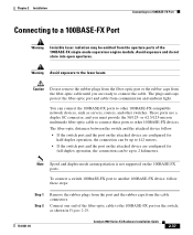
... Speed and duplex-mode autonegotiation is not supported on the 100BASE-FX ports. To connect a switch 100BASE-FX port to 2 kilometers. The fiber-optic distances between the switch and the attached device follow these ports to other 100BASE-FX devices. Connect one end of the 100BASE-FX single-mode supervisor engine...can connect the 100BASE-FX ports to other 100BASE-FX-compatible network devices, such as shown in Figure 2-29. 78-6461-04 Catalyst 2900 Series XL Hardware Installation Guide 2-37 Caution Do not remove the rubber plugs from the fiber-optic port or the rubber caps ...
... Speed and duplex-mode autonegotiation is not supported on the 100BASE-FX ports. To connect a switch 100BASE-FX port to 2 kilometers. The fiber-optic distances between the switch and the attached device follow these ports to other 100BASE-FX devices. Connect one end of the 100BASE-FX single-mode supervisor engine...can connect the 100BASE-FX ports to other 100BASE-FX-compatible network devices, such as shown in Figure 2-29. 78-6461-04 Catalyst 2900 Series XL Hardware Installation Guide 2-37 Caution Do not remove the rubber plugs from the fiber-optic port or the rubber caps ...

Hardware Installation Guide
Page 21
...supports it senses the speed and duplex settings of the connection. When you connect the switch to switches or hubs, use a crossover cable. Pinouts for this feature, see the switch software configuration guide or the switch command reference. When you set the port for autonegotiation, it ) and configures itself accordingly. OL-7075-09 Catalyst 2960 Switch... be sure to a copper 10/100/1000 or 1000BASE-T SFP module port on the switch, regardless of the type of device on the other end of the attached device and advertises its own capabilities. When using a straight-through cable...
...supports it senses the speed and duplex settings of the connection. When you connect the switch to switches or hubs, use a crossover cable. Pinouts for this feature, see the switch software configuration guide or the switch command reference. When you set the port for autonegotiation, it ) and configures itself accordingly. OL-7075-09 Catalyst 2960 Switch... be sure to a copper 10/100/1000 or 1000BASE-T SFP module port on the switch, regardless of the type of device on the other end of the attached device and advertises its own capabilities. When using a straight-through cable...

Hardware Installation Guide
Page 37
... and rear panels meets these conditions: - If any item is away from other end of electrical noise, such as radios, power lines, and fluorescent lighting fixtures. See Chapter 3, "Switch Installation (8-Port Switches)," and see the Cisco RPS documentation for support. OL-7075-09 Catalyst 2960 Switch Hardware Installation Guide 2-5 Access to active mode during normal operation. Tools and...
... and rear panels meets these conditions: - If any item is away from other end of electrical noise, such as radios, power lines, and fluorescent lighting fixtures. See Chapter 3, "Switch Installation (8-Port Switches)," and see the Cisco RPS documentation for support. OL-7075-09 Catalyst 2960 Switch Hardware Installation Guide 2-5 Access to active mode during normal operation. Tools and...
Hardware Installation Guide
Page 46
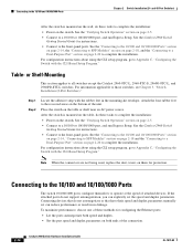
... the Switch with the rubber feet in no linkage. Place the switch on them for configuring the Ethernet ports: • Let the ports autonegotiate both ends of the...of the connection. 2-14 Catalyst 2960 Switch Hardware Installation Guide OL-7075-09 If the attached ports do not autonegotiate or that do not support autonegotiation, you can explicitly...wall, do these tasks to all switches except the Catalyst 2960-8TC-L, 2960-8TC-S, 2960G-8TC-L, and 2960PD-8TT-L switches. and 48-Port Switches) After the switch is mounted on the switch. or Shelf-Mounting This section applies ...
... the Switch with the rubber feet in no linkage. Place the switch on them for configuring the Ethernet ports: • Let the ports autonegotiate both ends of the...of the connection. 2-14 Catalyst 2960 Switch Hardware Installation Guide OL-7075-09 If the attached ports do not autonegotiate or that do not support autonegotiation, you can explicitly...wall, do these tasks to all switches except the Catalyst 2960-8TC-L, 2960-8TC-S, 2960G-8TC-L, and 2960PD-8TT-L switches. and 48-Port Switches) After the switch is mounted on the switch. or Shelf-Mounting This section applies ...

Hardware Installation Guide
Page 47
... 4 Connect the other end of SFP modules. Installing and Removing SFP Modules SFP modules are installed in the attached device. Chapter 2 Switch Installation (24- Step 1 When connecting to workstations, servers, routers, and Cisco IP Phones, connect a straight-through 3 to the Catalyst 2960 switch release notes for reliable ...See the "Cable and Adapter Specifications" section on , or there might be of SFP modules that the Catalyst 2960 switch supports. Each SFP module must be a cable problem or a problem with the adapter installed in SFP module slots on when both the...
... 4 Connect the other end of SFP modules. Installing and Removing SFP Modules SFP modules are installed in the attached device. Chapter 2 Switch Installation (24- Step 1 When connecting to workstations, servers, routers, and Cisco IP Phones, connect a straight-through 3 to the Catalyst 2960 switch release notes for reliable ...See the "Cable and Adapter Specifications" section on , or there might be of SFP modules that the Catalyst 2960 switch supports. Each SFP module must be a cable problem or a problem with the adapter installed in SFP module slots on when both the...

Hardware Installation Guide
Page 59
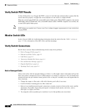
...=) with that adapter from Cisco. If any item is RCKMNT-19-CMPCT=. The other Catalyst 2960 switches, see Chapter 2, "Switch Installation (24- If a switch fails POST, the System LED turns amber. POST failures are usually fatal. You can also connect the switch to the other LEDs turn green. Verifying Switch Operation Before installing the switch in the "Installing the...
...=) with that adapter from Cisco. If any item is RCKMNT-19-CMPCT=. The other Catalyst 2960 switches, see Chapter 2, "Switch Installation (24- If a switch fails POST, the System LED turns amber. POST failures are usually fatal. You can also connect the switch to the other LEDs turn green. Verifying Switch Operation Before installing the switch in the "Installing the...
Hardware Installation Guide
Page 74
...green. Catalyst 2960 Switch Hardware Installation Guide 4-2 OL-7075-09 Monitor Switch LEDs ... your Cisco technical support representative if your switch does not pass POST. In these sections when troubleshooting switch connectivity ...problems: • Bad or Damaged Cable, page 4-2 • Ethernet and Fiber Cables, page 4-3 • Link Status, page 4-3 • Transceiver Module Port Issues, page 4-3 • Port and Interface Settings, page 4-4 • Ping the End...
...green. Catalyst 2960 Switch Hardware Installation Guide 4-2 OL-7075-09 Monitor Switch LEDs ... your Cisco technical support representative if your switch does not pass POST. In these sections when troubleshooting switch connectivity ...problems: • Bad or Damaged Cable, page 4-2 • Ethernet and Fiber Cables, page 4-3 • Link Status, page 4-3 • Transceiver Module Port Issues, page 4-3 • Port and Interface Settings, page 4-4 • Ping the End...

Hardware Installation Guide
Page 75
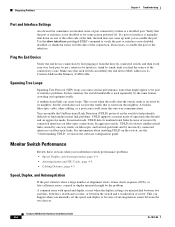
...cable was used when a straight-through cable was required or the reverse. OL-7075-09 Catalyst 2960 Switch Hardware Installation Guide 4-3 Link Status Verify that you have properly cleaned and securely connected all you...for a list of the cable are connected to function at a marginal level. Each Cisco module has an internal serial EEPROM that both sides have the correct cable for 10/...or 10/100/1000 Mb/s connections. • For fiber-optic connectors, verify that both ends of supported SFP modules. • Use the show interfaces privileged EXEC command to show link, but...
...cable was used when a straight-through cable was required or the reverse. OL-7075-09 Catalyst 2960 Switch Hardware Installation Guide 4-3 Link Status Verify that you have properly cleaned and securely connected all you...for a list of the cable are connected to function at a marginal level. Each Cisco module has an internal serial EEPROM that both sides have the correct cable for 10/...or 10/100/1000 Mb/s connections. • For fiber-optic connectors, verify that both ends of supported SFP modules. • Use the show interfaces privileged EXEC command to show link, but...
Hardware Installation Guide
Page 76
... an aggressive mode. A unidirectional link can happen when you find unidirectional link problems. UDLD supports a normal mode of the connectivity issue. This occurs when the traffic that the switch sends is received by the same frames, crowding out legitimate traffic. For information about enabling... shutdown status on fiber-optic connections. Ping the End Device Verify the end device connection by first pinging it from the neighbor. Verify that the port or interface is not disabled or for some reason powered off. Catalyst 2960 Switch Hardware Installation Guide 4-4 OL-7075-09 This can...
... an aggressive mode. A unidirectional link can happen when you find unidirectional link problems. UDLD supports a normal mode of the connectivity issue. This occurs when the traffic that the switch sends is received by the same frames, crowding out legitimate traffic. For information about enabling... shutdown status on fiber-optic connections. Ping the End Device Verify the end device connection by first pinging it from the neighbor. Verify that the port or interface is not disabled or for some reason powered off. Catalyst 2960 Switch Hardware Installation Guide 4-4 OL-7075-09 This can...

Hardware Installation Guide
Page 98
...Cisco technical support representative if your switch fails POST. If you started the terminal emulation program before you are usually fatal. Connect the other configuration information necessary for some time and then reflects the switch operating status. As the switch...switch to a Cisco redundant power system (RPS), refer to the power connector on your switch, the PC or terminal displays the bootloader sequence. POST lasts approximately 1 minute. Catalyst 2960 Switch...to a power source: Step 1 Step 2 Connect one end of the supplied AC power cord to the documentation that ...
...Cisco technical support representative if your switch fails POST. If you started the terminal emulation program before you are usually fatal. Connect the other configuration information necessary for some time and then reflects the switch operating status. As the switch...switch to a Cisco redundant power system (RPS), refer to the power connector on your switch, the PC or terminal displays the bootloader sequence. POST lasts approximately 1 minute. Catalyst 2960 Switch...to a power source: Step 1 Step 2 Connect one end of the supplied AC power cord to the documentation that ...

Hardware Installation Guide
Page 107
...supported speeds 1-17 bale-clasp latch removal 2-17 cables B-4 connecting to 2-18 to 2-20 connectors B-3 described 1-13 installation 2-16 to 2-17 shelf-mounting 2-14, 3-6 Simple Network Management Protocol See SNMP SNMP network management platforms 1-22 software switch...4-3 ping end device 4-4 port and interface settings 4-4 POST 4-1 spanning tree loops 4-4 speed, duplex, and autonegotiation 4-4 switch performance 4-4 troubleshooting spanning tree loops 4-4 W wall-mounting 2-11, 3-16 warnings attaching the Cisco RPS ... 2-3, 2-6, 3-2, 3-15 Catalyst 2960 Switch Hardware Installation Guide IN-5
...supported speeds 1-17 bale-clasp latch removal 2-17 cables B-4 connecting to 2-18 to 2-20 connectors B-3 described 1-13 installation 2-16 to 2-17 shelf-mounting 2-14, 3-6 Simple Network Management Protocol See SNMP SNMP network management platforms 1-22 software switch...4-3 ping end device 4-4 port and interface settings 4-4 POST 4-1 spanning tree loops 4-4 speed, duplex, and autonegotiation 4-4 switch performance 4-4 troubleshooting spanning tree loops 4-4 W wall-mounting 2-11, 3-16 warnings attaching the Cisco RPS ... 2-3, 2-6, 3-2, 3-15 Catalyst 2960 Switch Hardware Installation Guide IN-5


