

Hardware Installation Guide
Page 24
... user interface that is already installed on the model, the switch front panels can have a set of LEDs and a Mode button. The switch supports a comprehensive set of MIB extensions and four Remote Monitoring (RMON) groups. Catalyst 2900 Series XL Hardware Installation Guide 1-4 78-6461-04 You can also display network topologies to gather link information and to display switch images to the Catalyst 2900 Series XL and Catalyst 3500 Series XL Software Configuration Guide. You can fully configure and monitor a standalone switch, a specific...
... user interface that is already installed on the model, the switch front panels can have a set of LEDs and a Mode button. The switch supports a comprehensive set of MIB extensions and four Remote Monitoring (RMON) groups. Catalyst 2900 Series XL Hardware Installation Guide 1-4 78-6461-04 You can also display network topologies to gather link information and to display switch images to the Catalyst 2900 Series XL and Catalyst 3500 Series XL Software Configuration Guide. You can fully configure and monitor a standalone switch, a specific...

Hardware Installation Guide
Page 26
... 5 cabling Note A Category 5 cable is required for more info on the Catalyst 2900 XL switches provide protocol support for autonegotiation, the port senses the speed and duplex settings of half duplex, full duplex, 10 Mbps, or 100 Mbps. When connecting the switch to workstations, servers, routers, and Cisco IP Phones, be connected to the Catalyst 3500 Series XL Hardware Installation Guide. The 10/100 ports on the Catalyst 3524-PWR XL switch, refer to an AC power...
... 5 cabling Note A Category 5 cable is required for more info on the Catalyst 2900 XL switches provide protocol support for autonegotiation, the port senses the speed and duplex settings of half duplex, full duplex, 10 Mbps, or 100 Mbps. When connecting the switch to workstations, servers, routers, and Cisco IP Phones, be connected to the Catalyst 3500 Series XL Hardware Installation Guide. The 10/100 ports on the Catalyst 3524-PWR XL switch, refer to an AC power...
Hardware Installation Guide
Page 89
... check the most important system components before the switch begins forwarding packets. See the Catalyst 2900 Series XL and Catalyst 3500 Series XL Software Configuration Guide, the Catalyst 2900 Series XL and Catalyst 3500 Series XL Command Reference, or the documentation that came with number 1x. When the switch begins its POST, the port status LEDs turn amber for troubleshooting problems: • Understanding POST Results • Diagnosing Problems Understanding POST Results Each time the switch is powered on self-test (POST), port-connectivity problems...
... check the most important system components before the switch begins forwarding packets. See the Catalyst 2900 Series XL and Catalyst 3500 Series XL Software Configuration Guide, the Catalyst 2900 Series XL and Catalyst 3500 Series XL Command Reference, or the documentation that came with number 1x. When the switch begins its POST, the port status LEDs turn amber for troubleshooting problems: • Understanding POST Results • Diagnosing Problems Understanding POST Results Each time the switch is powered on self-test (POST), port-connectivity problems...

Hardware Installation Guide
Page 22
... monitoring PoE ports, see the documentation that do not fully support IEEE 802.3af, might switch to it. For information about Cisco IP Phones and Cisco Aironet Access Points, see the switch software configuration guide. The Catalyst 2960-24LT-L and 2960-24LC-S switches deliver a maximum power output of PoE. Auto: When you can be accessed only through the use of a special tool, lock and key or other means of approximately 370-W PoE power. The Auto setting is connected...
... monitoring PoE ports, see the documentation that do not fully support IEEE 802.3af, might switch to it. For information about Cisco IP Phones and Cisco Aironet Access Points, see the switch software configuration guide. The Catalyst 2960-24LT-L and 2960-24LC-S switches deliver a maximum power output of PoE. Auto: When you can be accessed only through the use of a special tool, lock and key or other means of approximately 370-W PoE power. The Auto setting is connected...
Hardware Installation Guide
Page 32
... configure and monitor the switch and switch cluster members from an SNMP-compatible workstation that offers quick configuration and monitoring. The software configuration guide also provides examples of network configuration concepts. For more information. You can be downloaded from a remote management station. You can access the CLI either by using Telnet from this URL: http://www.cisco.com/go/cna For information on starting Network Assistant, see the device manager online help. • Cisco IOS command-line interface (CLI) The switch CLI...
... configure and monitor the switch and switch cluster members from an SNMP-compatible workstation that offers quick configuration and monitoring. The software configuration guide also provides examples of network configuration concepts. For more information. You can be downloaded from a remote management station. You can access the CLI either by using Telnet from this URL: http://www.cisco.com/go/cna For information on starting Network Assistant, see the device manager online help. • Cisco IOS command-line interface (CLI) The switch CLI...

Hardware Installation Guide
Page 36
... the Catalyst 2960 8-port switches. Avoid using uninsulated exposed metal contacts, conductors, or terminals. Statement 1073 Warning Installation of the equipment must be no longer than 328 feet (100 meters). • The cables meet the specifications in Table B-1 on Power over Ethernet (PoE) circuits if interconnections are made using such interconnection methods, unless the exposed metal parts are located within a restricted access location and users and service people...
... the Catalyst 2960 8-port switches. Avoid using uninsulated exposed metal contacts, conductors, or terminals. Statement 1073 Warning Installation of the equipment must be no longer than 328 feet (100 meters). • The cables meet the specifications in Table B-1 on Power over Ethernet (PoE) circuits if interconnections are made using such interconnection methods, unless the exposed metal parts are located within a restricted access location and users and service people...

Hardware Installation Guide
Page 37
... power source. Chapter 2 Switch Installation (24- See Chapter 3, "Switch Installation (8-Port Switches)," and see the Cisco RPS documentation for support. Set the RPS to rack-mount the switch. Access to an AC power outlet. If any item is unrestricted. • Temperature around it might need to supply a number-2 Phillips screwdriver to active mode during normal operation. To power on the switch, connect one end of electrical noise, such as radios, power lines, and fluorescent lighting...
... power source. Chapter 2 Switch Installation (24- See Chapter 3, "Switch Installation (8-Port Switches)," and see the Cisco RPS documentation for support. Set the RPS to rack-mount the switch. Access to an AC power outlet. If any item is unrestricted. • Temperature around it might need to supply a number-2 Phillips screwdriver to active mode during normal operation. To power on the switch, connect one end of electrical noise, such as radios, power lines, and fluorescent lighting...

Hardware Installation Guide
Page 47
... the cable to cabling problems. Reconfigure and reboot the connected device if necessary. The auto-MDIX feature is amber while Spanning Tree Protocol (STP) discovers the topology and searches for cable OL-7075-09 Catalyst 2960 Switch Hardware Installation Guide 2-15 The port LED turns on page B-4 for loops. See Chapter 4, "Troubleshooting," for this feature, see the switch software configuration guide or the switch command reference. If the port LED does not turn on the other end of SFP modules that the Catalyst 2960 switch supports. Chapter 2 Switch Installation...
... the cable to cabling problems. Reconfigure and reboot the connected device if necessary. The auto-MDIX feature is amber while Spanning Tree Protocol (STP) discovers the topology and searches for cable OL-7075-09 Catalyst 2960 Switch Hardware Installation Guide 2-15 The port LED turns on page B-4 for loops. See Chapter 4, "Troubleshooting," for this feature, see the switch software configuration guide or the switch command reference. If the port LED does not turn on the other end of SFP modules that the Catalyst 2960 switch supports. Chapter 2 Switch Installation...
Hardware Installation Guide
Page 48
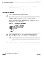
... of the potential damage to your SFP module documentation. Use only Cisco SFP modules on the module snap into place in front of the slot. Disconnect all cables before removing or installing an SFP module. Step 3 Step 4 Align the SFP module in the rear of the slot opening. See Figure 2-15. 2-16 Catalyst 2960 Switch Hardware Installation Guide OL-7075-09 and 48-Port Switches) stipulations for SFP module connections. Only SFP modules with a Bale-Clasp Latch 86575...
... of the potential damage to your SFP module documentation. Use only Cisco SFP modules on the module snap into place in front of the slot. Disconnect all cables before removing or installing an SFP module. Step 3 Step 4 Align the SFP module in the rear of the slot opening. See Figure 2-15. 2-16 Catalyst 2960 Switch Hardware Installation Guide OL-7075-09 and 48-Port Switches) stipulations for SFP module connections. Only SFP modules with a Bale-Clasp Latch 86575...

Hardware Installation Guide
Page 53
... can use web interface that offers quick configuration and monitoring. See the Catalyst 2960 Switch Software Configuration Guide and the Catalyst 2960 Switch Command Reference on Cisco.com for information on using the media type interface configuration command. For more information, see the device manager online help. • Start the Network Assistant application, which is described in the Getting Started with a Catalyst 2960 switch. • Start an SNMP application such as an individual switch. OL-7075-09 Catalyst 2960 Switch Hardware Installation Guide 2-21 and 48-Port...
... can use web interface that offers quick configuration and monitoring. See the Catalyst 2960 Switch Software Configuration Guide and the Catalyst 2960 Switch Command Reference on Cisco.com for information on using the media type interface configuration command. For more information, see the device manager online help. • Start the Network Assistant application, which is described in the Getting Started with a Catalyst 2960 switch. • Start an SNMP application such as an individual switch. OL-7075-09 Catalyst 2960 Switch Hardware Installation Guide 2-21 and 48-Port...

Hardware Installation Guide
Page 56
.... Statement 43 Warning Do not stack the chassis on the system or connect or disconnect cables during periods of the rack if it can cause serious burns or weld the metal object to power lines, remove jewelry (including rings, necklaces, and watches). Statement 1019 Catalyst 2960 Switch Hardware Installation Guide 3-2 OL-7075-09 Preparing for Installation Chapter 3 Switch Installation (8-Port Switches) Warning Before working on equipment that the system...
.... Statement 43 Warning Do not stack the chassis on the system or connect or disconnect cables during periods of the rack if it can cause serious burns or weld the metal object to power lines, remove jewelry (including rings, necklaces, and watches). Statement 1019 Catalyst 2960 Switch Hardware Installation Guide 3-2 OL-7075-09 Preparing for Installation Chapter 3 Switch Installation (8-Port Switches) Warning Before working on equipment that the system...

Hardware Installation Guide
Page 57
...-09 Catalyst 2960 Switch Hardware Installation Guide 3-3 Statement 1040. Statement 1073 Warning Installation of the equipment must comply with integral circuit protection: 10/100/1000 Ethernet. and 48-Port Switches)." Do not open. Warning For connections outside the building where the equipment is installed, the following ports must be handled according to all national laws and regulations. Statement 1044 Warning When installing or replacing the...
...-09 Catalyst 2960 Switch Hardware Installation Guide 3-3 Statement 1040. Statement 1073 Warning Installation of the equipment must comply with integral circuit protection: 10/100/1000 Ethernet. and 48-Port Switches)." Do not open. Warning For connections outside the building where the equipment is installed, the following ports must be handled according to all national laws and regulations. Statement 1044 Warning When installing or replacing the...

Hardware Installation Guide
Page 58
... these part numbers: • Catalyst 2960-8TC-L, 2960-8TC-S, and 2960PD-8TT-L switches cable guard part number: CBLGRD-C2960-8TC= • Catalyst 2960G-8TC-L switch cable guard part number: CBLGRD-C2960G-8TC= The cable guard is used to secure a laptop computer, to avoid overloading the receiver. Catalyst 2960 Switch Hardware Installation Guide 3-4 OL-7075-09 and 48-Port Switches)." The switch has security slots in the link to secure either or both sides of cables in the rack. • Do not wall-mount the switch...
... these part numbers: • Catalyst 2960-8TC-L, 2960-8TC-S, and 2960PD-8TT-L switches cable guard part number: CBLGRD-C2960-8TC= • Catalyst 2960G-8TC-L switch cable guard part number: CBLGRD-C2960G-8TC= The cable guard is used to secure a laptop computer, to avoid overloading the receiver. Catalyst 2960 Switch Hardware Installation Guide 3-4 OL-7075-09 and 48-Port Switches)." The switch has security slots in the link to secure either or both sides of cables in the rack. • Do not wall-mount the switch...

Hardware Installation Guide
Page 59
...-inch rack-mounting brackets and hardware from an upstream PoE switch. If a switch fails POST, the System LED turns amber. To power on the switch, connect one end of the AC power cord to the AC power connector on the switch, and connect the other Catalyst 2960 switches, see Chapter 2, "Switch Installation (24- LEDs can receive power from Cisco. Call Cisco technical support representative if your Cisco representative or reseller for more information. For information applicable to the Catalyst 2960 8-port switches...
...-inch rack-mounting brackets and hardware from an upstream PoE switch. If a switch fails POST, the System LED turns amber. To power on the switch, connect one end of the AC power cord to the AC power connector on the switch, and connect the other Catalyst 2960 switches, see Chapter 2, "Switch Installation (24- LEDs can receive power from Cisco. Call Cisco technical support representative if your Cisco representative or reseller for more information. For information applicable to the Catalyst 2960 8-port switches...

Hardware Installation Guide
Page 69
... Catalyst 2960 8-port switches. Chapter 3 Switch Installation (8-Port Switches) Installing the Switch Rack-Mounting This section is specific to the opposite side. Warning To prevent bodily injury when mounting or servicing this unit in a rack, you must take special precautions to the other Catalyst 2960 switches, see Chapter 2, "Switch Installation (24- and 48-Port Switches)." The kit part number is the only unit in the rack. • When mounting this unit in a partially filled rack, load the rack from Cisco...
... Catalyst 2960 8-port switches. Chapter 3 Switch Installation (8-Port Switches) Installing the Switch Rack-Mounting This section is specific to the opposite side. Warning To prevent bodily injury when mounting or servicing this unit in a rack, you must take special precautions to the other Catalyst 2960 switches, see Chapter 2, "Switch Installation (24- and 48-Port Switches)." The kit part number is the only unit in the rack. • When mounting this unit in a partially filled rack, load the rack from Cisco...
Hardware Installation Guide
Page 73
... on page 4-2 • "Monitor Switch Performance" section on Cisco.com or the documentation that came with your SNMP application for troubleshooting problems: • Diagnosing Problems, page 4-1 • Clearing the Switch IP Address and Configuration, page 4-5 • Locating the Switch Serial Number, page 4-6 Diagnosing Problems The LEDs on self-test (POST), port-connectivity problems, and overall switch performance. See the software configuration guide and the switch command reference on page 4-4 OL-7075-09 Catalyst 2960 Switch Hardware Installation Guide 4-1 Troubleshooting...
... on page 4-2 • "Monitor Switch Performance" section on Cisco.com or the documentation that came with your SNMP application for troubleshooting problems: • Diagnosing Problems, page 4-1 • Clearing the Switch IP Address and Configuration, page 4-5 • Locating the Switch Serial Number, page 4-6 Diagnosing Problems The LEDs on self-test (POST), port-connectivity problems, and overall switch performance. See the software configuration guide and the switch command reference on page 4-4 OL-7075-09 Catalyst 2960 Switch Hardware Installation Guide 4-1 Troubleshooting...
Hardware Installation Guide
Page 77
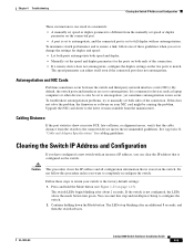
...-09 Catalyst 2960 Switch Hardware Installation Guide 4-5 It is common for cabling guidelines. Chapter 4 Troubleshooting Clearing the Switch IP Address and Configuration These circumstances can result in a mismatch: • A manually set speed or duplex parameter is different from the manually set speed or duplex parameter on page 1-15). The LEDs stop blinking after about 2 seconds. Press and hold the Mode button (see Figure 1-23 on the connected port. • A port is set to autonegotiate, and the connected port is set to...
...-09 Catalyst 2960 Switch Hardware Installation Guide 4-5 It is common for cabling guidelines. Chapter 4 Troubleshooting Clearing the Switch IP Address and Configuration These circumstances can result in a mismatch: • A manually set speed or duplex parameter is different from the manually set speed or duplex parameter on page 1-15). The LEDs stop blinking after about 2 seconds. Press and hold the Mode button (see Figure 1-23 on the connected port. • A port is set to autonegotiate, and the connected port is set to...

Hardware Installation Guide
Page 98
... manage the switch. The other configuration information necessary for some time and then reflects the switch operating status. Catalyst 2960 Switch Hardware Installation Guide C-4 OL-7075-09 Connecting to a Power Source Appendix C Configuring the Switch with the CLI-Based Setup Program Step 3 Configure the baud rate and character format of the PC or terminal to match these console port default characteristics: • 9600 baud • 8 data bits • 1 stop bit • No parity • None (flow control) Connecting...
... manage the switch. The other configuration information necessary for some time and then reflects the switch operating status. Catalyst 2960 Switch Hardware Installation Guide C-4 OL-7075-09 Connecting to a Power Source Appendix C Configuring the Switch with the CLI-Based Setup Program Step 3 Configure the baud rate and character format of the PC or terminal to match these console port default characteristics: • 9600 baud • 8 data bits • 1 stop bit • No parity • None (flow control) Connecting...

Hardware Installation Guide
Page 100
... CLI-Based Setup Program Step 6 (Optional) Configure Simple Network Management Protocol (SNMP) by entering the switch IP address and subnet mask and pressing Return. Catalyst 2960 Switch Hardware Installation Guide C-6 OL-7075-09 You can also configure SNMP later through the CLI, the device manager, or the Network Assistant application. Would you enter N, the switch appears as that appears: The following configuration command script was created: hostname switch1 enable secret 5 $1$Ulq8$DlA/OiaEbl90WcBPd9cOn1 enable password enable_password line...
... CLI-Based Setup Program Step 6 (Optional) Configure Simple Network Management Protocol (SNMP) by entering the switch IP address and subnet mask and pressing Return. Catalyst 2960 Switch Hardware Installation Guide C-6 OL-7075-09 You can also configure SNMP later through the CLI, the device manager, or the Network Assistant application. Would you enter N, the switch appears as that appears: The following configuration command script was created: hostname switch1 enable secret 5 $1$Ulq8$DlA/OiaEbl90WcBPd9cOn1 enable password enable_password line...

Hardware Installation Guide
Page 107
... 3-2 disconnecting device 2-3 Ethernet cables 2-2, 3-2 Ethernet ports 3-3 ground connection 2-4, 3-3 grounded equipment 2-3, 3-3 installation 2-2, 3-1 installation instructions 2-2, 3-2 jewelry removal 2-2, 3-2 lightning activity 2-2, 3-2 local and national electrical codes compliance 2-4, 3-3 more than one power supply 3-3 no user-serviceable parts 2-4 overheating prevention 2-2, 3-1 plug-socket combination 2-3 PoE 3-2 power supplies 2-3 prevent bodily injury 2-3, 2-6, 3-2, 3-15 product disposal 2-3, 3-3 rack-mounting 2-3, 2-6, 3-2, 3-15 Catalyst 2960 Switch Hardware Installation Guide IN-5
... 3-2 disconnecting device 2-3 Ethernet cables 2-2, 3-2 Ethernet ports 3-3 ground connection 2-4, 3-3 grounded equipment 2-3, 3-3 installation 2-2, 3-1 installation instructions 2-2, 3-2 jewelry removal 2-2, 3-2 lightning activity 2-2, 3-2 local and national electrical codes compliance 2-4, 3-3 more than one power supply 3-3 no user-serviceable parts 2-4 overheating prevention 2-2, 3-1 plug-socket combination 2-3 PoE 3-2 power supplies 2-3 prevent bodily injury 2-3, 2-6, 3-2, 3-15 product disposal 2-3, 3-3 rack-mounting 2-3, 2-6, 3-2, 3-15 Catalyst 2960 Switch Hardware Installation Guide IN-5


