

Hardware Installation Guide
Page 9
INDEX Class 1 Laser Product Warning C-22 Laser Beam Exposure Warning C-23 No On/Off Switch Warning C-24 Chassis Warning-Rack-Mounting and Servicing C-25 Reinforced Insulation Warning C-29 LAN Connections Only Warning C-30 No Field-Replaceable Units Warning C-31 Installation Warning C-32 SELV Source Warning C-33 ... Equipment Warning C-36 Ground Connection Warning C-37 Qualified Personnel Warning C-38 DC Power Disconnection Warning C-39 Exposed Wire Lead Warning C-41 Contents 78-6461-04 Catalyst 2900 Series XL Hardware Installation Guide ix
INDEX Class 1 Laser Product Warning C-22 Laser Beam Exposure Warning C-23 No On/Off Switch Warning C-24 Chassis Warning-Rack-Mounting and Servicing C-25 Reinforced Insulation Warning C-29 LAN Connections Only Warning C-30 No Field-Replaceable Units Warning C-31 Installation Warning C-32 SELV Source Warning C-33 ... Equipment Warning C-36 Ground Connection Warning C-37 Qualified Personnel Warning C-38 DC Power Disconnection Warning C-39 Exposed Wire Lead Warning C-41 Contents 78-6461-04 Catalyst 2900 Series XL Hardware Installation Guide ix

Hardware Installation Guide
Page 52
... does not attach to the Catalyst 2912 LRE XL and 2924 LRE XL switches. • One RJ-45-to-DB-9 adapter • Cisco Information Packet, containing warranty, safety, and support information Note In addition to the switch (24-inch rack mount) - Two mounting brackets - One cable guide and one (two for modular switches) black Phillips machine screw for...
... does not attach to the Catalyst 2912 LRE XL and 2924 LRE XL switches. • One RJ-45-to-DB-9 adapter • Cisco Information Packet, containing warranty, safety, and support information Note In addition to the switch (24-inch rack mount) - Two mounting brackets - One cable guide and one (two for modular switches) black Phillips machine screw for...
Hardware Installation Guide
Page 53
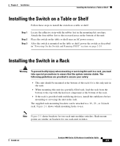
...with stabilizing devices, install the stabilizers before mounting or servicing the unit in a rack, you must take special precautions to use. Note Figure 2-1 shows brackets for one-rack-unit switches. 78-6461-04 Catalyst 2900 Series XL Hardware Installation Guide 2-9... Attach the four rubber feet to the top with the heaviest component at the bottom of the unit. Figure 2-1 shows which mounting holes to ensure that the system remains stable. Place the switch on the table or shelf near an AC power source. The supplied rack-mounting...
...with stabilizing devices, install the stabilizers before mounting or servicing the unit in a rack, you must take special precautions to use. Note Figure 2-1 shows brackets for one-rack-unit switches. 78-6461-04 Catalyst 2900 Series XL Hardware Installation Guide 2-9... Attach the four rubber feet to the top with the heaviest component at the bottom of the unit. Figure 2-1 shows which mounting holes to ensure that the system remains stable. Place the switch on the table or shelf near an AC power source. The supplied rack-mounting...

Hardware Installation Guide
Page 54
... XL, and 2924M XL DC Switches 19" rack mount point 24" rack 23" rack mount point mount point 47307 19" rack mount point 24" rack 23" rack mount point mount point Figure 2-2 Mounting Brackets Points for Catalyst 2912 LRE XL and 2924 LRE XL Switches 19" rack mount point 24" rack 23" rack mount point mount point 54725 19" rack mount point 24" rack 23" rack mount point mount point To install the switch in these procedures: • "Removing...
... XL, and 2924M XL DC Switches 19" rack mount point 24" rack 23" rack mount point mount point 47307 19" rack mount point 24" rack 23" rack mount point mount point Figure 2-2 Mounting Brackets Points for Catalyst 2912 LRE XL and 2924 LRE XL Switches 19" rack mount point 24" rack 23" rack mount point mount point 54725 19" rack mount point 24" rack 23" rack mount point mount point To install the switch in these procedures: • "Removing...
Hardware Installation Guide
Page 60
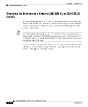
... to one side of the switch. 2-16 Catalyst 2900 Series XL Hardware Installation Guide 78-6461-04 If you install the switch in a 19-inch rack. Installing the Switch in a Rack Chapter 2 Installation Attaching the Brackets to a Catalyst 2912 LRE XL or 2924 LRE XL Switch A Catalyst 2912 LRE XL or 2924 LRE XL switch can only be rack-mounted in a 23-
... to one side of the switch. 2-16 Catalyst 2900 Series XL Hardware Installation Guide 78-6461-04 If you install the switch in a 19-inch rack. Installing the Switch in a Rack Chapter 2 Installation Attaching the Brackets to a Catalyst 2912 LRE XL or 2924 LRE XL Switch A Catalyst 2912 LRE XL or 2924 LRE XL switch can only be rack-mounted in a 23-

Hardware Installation Guide
Page 69
...pound-force inches (lbf-in.) of action. If a test fails, the port LED associated with number 1, turn off . Call Cisco Systems immediately if your switch does not pass POST. Step 1 Step 2 Unpack the shipping box, and verify its contents. Obtain the following necessary tools and ...-input power source, follow the steps in these steps before rack-mounting and grounding the switch or wiring it to the items described in the Catalyst 2900 Series XL Installation Guide, the switch is shipped with a Phillips head that the switch is operational. In addition to a DC-input power source...
...pound-force inches (lbf-in.) of action. If a test fails, the port LED associated with number 1, turn off . Call Cisco Systems immediately if your switch does not pass POST. Step 1 Step 2 Unpack the shipping box, and verify its contents. Obtain the following necessary tools and ...-input power source, follow the steps in these steps before rack-mounting and grounding the switch or wiring it to the items described in the Catalyst 2900 Series XL Installation Guide, the switch is shipped with a Phillips head that the switch is operational. In addition to a DC-input power source...

Hardware Installation Guide
Page 157
... statements 2-4 to 2-6 expansion slots LEDs 1-19 supported modules 1-8 exposed wire lead warning C-41 F feedback to 2-41 78-6461-04 Catalyst 2900 Series XL Hardware Installation Guide IN-3 or 62.5/125-micron 2-37, B-2 front panel 10/100 ports 1-6 expansion slots 1-8 fixed ... ports 1-6 LED 1-16 port mode 1-16 hot-swappable modules 1-8 HP OpenView 1-4 I installation attaching mounting brackets (rack-mount) 2-11, 2-16 attaching mounting brackets (telco rack-mount) 2-15 attaching mounting brackets (wall-mount) 2-22 cable guide 2-19 connecting to 10/100BASE-T ports 2-35 100BASE-FX ports 2-37 to...
... statements 2-4 to 2-6 expansion slots LEDs 1-19 supported modules 1-8 exposed wire lead warning C-41 F feedback to 2-41 78-6461-04 Catalyst 2900 Series XL Hardware Installation Guide IN-3 or 62.5/125-micron 2-37, B-2 front panel 10/100 ports 1-6 expansion slots 1-8 fixed ... ports 1-6 LED 1-16 port mode 1-16 hot-swappable modules 1-8 HP OpenView 1-4 I installation attaching mounting brackets (rack-mount) 2-11, 2-16 attaching mounting brackets (telco rack-mount) 2-15 attaching mounting brackets (wall-mount) 2-22 cable guide 2-19 connecting to 10/100BASE-T ports 2-35 100BASE-FX ports 2-37 to...

Hardware Installation Guide
Page 158
Index console port connecting to 2-42 to 2-43 electrical noise, avoiding 2-7 guidelines 2-6 mounting in a rack 2-18 to 2-19 mounting on a wall 2-22 to 2-24 packing list 2-7 rack-mount 2-18 to 2-19 table or shelf 2-9 wall-mount 2-22 to 2-24 warnings 2-1 to 2-4 installation guidelines 2-6 IP Phones connecting to 10/100 ports 2-35 to 2-36 J ...100 port mode 1-14 to 1-16 expansion slots 1-19 FDUP 1-14 to 1-16 full duplex 1-16 half duplex 1-16 interpreting 1-14 LRE 1-15 port (Catalyst 2900 LRE XL) 1-17 port status 1-9, 1-16 to 1-18 POST results 2-24, 3-1 RPS 1-13 to 1-14 RPS 600 1-13 SPEED 1-15 STAT...
Index console port connecting to 2-42 to 2-43 electrical noise, avoiding 2-7 guidelines 2-6 mounting in a rack 2-18 to 2-19 mounting on a wall 2-22 to 2-24 packing list 2-7 rack-mount 2-18 to 2-19 table or shelf 2-9 wall-mount 2-22 to 2-24 warnings 2-1 to 2-4 installation guidelines 2-6 IP Phones connecting to 10/100 ports 2-35 to 2-36 J ...100 port mode 1-14 to 1-16 expansion slots 1-19 FDUP 1-14 to 1-16 full duplex 1-16 half duplex 1-16 interpreting 1-14 LRE 1-15 port (Catalyst 2900 LRE XL) 1-17 port status 1-9, 1-16 to 1-18 POST results 2-24, 3-1 RPS 1-13 to 1-14 RPS 600 1-13 SPEED 1-15 STAT...
Hardware Installation Guide
Page 159
mid-mount See installation attaching mounting brackets (telco rack-mount) modules 1-8 mounting brackets 2-9 attaching 2-11, 2-15, 2-22 N no on/off switch warning C-24 O overtemperature warning C-9 P PC, connecting to switch 2-42 performance problems, solving 3-3 personnel warning C-3 pinouts 10/100BASE-T ports B-2... cable, straight-through and crossover B-4 RJ-21 connector B-5 RJ-45-to-DB-25 terminal adapter B-8 RJ-45-to-DB-9 terminal adapter B-7 rollover cable B-7, B-8 Index port LEDs Catalyst ...
mid-mount See installation attaching mounting brackets (telco rack-mount) modules 1-8 mounting brackets 2-9 attaching 2-11, 2-15, 2-22 N no on/off switch warning C-24 O overtemperature warning C-9 P PC, connecting to switch 2-42 performance problems, solving 3-3 personnel warning C-3 pinouts 10/100BASE-T ports B-2... cable, straight-through and crossover B-4 RJ-21 connector B-5 RJ-45-to-DB-25 terminal adapter B-8 RJ-45-to-DB-9 terminal adapter B-7 rollover cable B-7, B-8 Index port LEDs Catalyst ...
Hardware Installation Guide
Page 4
... Equipment 3-5 Verifying Switch Operation 3-5 Installing the Switch 3-5 Catalyst 2960 Switch Hardware Installation Guide iv OL-7075-09 Contents 2 C H A P T E R 3 C H A P T E R Switch Installation (24- and 48-Port Switches) 2-1 Preparing for Installation 2-1 Warnings 2-2 Guidelines for Particulate Matter 2-4 Installation Guidelines 2-4 Box Contents 2-5 Tools and Equipment 2-5 Verifying Switch Operation 2-5 Installing the Switch 2-6 Rack-Mounting 2-6 Removing Screws from the Switch 2-7 Attaching Brackets to the Catalyst 2960 Switch 2-7 Mounting the Switch in a Rack 2-10 Attaching the...
... Equipment 3-5 Verifying Switch Operation 3-5 Installing the Switch 3-5 Catalyst 2960 Switch Hardware Installation Guide iv OL-7075-09 Contents 2 C H A P T E R 3 C H A P T E R Switch Installation (24- and 48-Port Switches) 2-1 Preparing for Installation 2-1 Warnings 2-2 Guidelines for Particulate Matter 2-4 Installation Guidelines 2-4 Box Contents 2-5 Tools and Equipment 2-5 Verifying Switch Operation 2-5 Installing the Switch 2-6 Rack-Mounting 2-6 Removing Screws from the Switch 2-7 Attaching Brackets to the Catalyst 2960 Switch 2-7 Mounting the Switch in a Rack 2-10 Attaching the...

Hardware Installation Guide
Page 5
...-T- and 100BASE-TX-Compatible Devices B-1 Connecting to the Switch 3-15 Mounting the Switch in a 19-Inch Rack 3-16 Wall-Mounting (with Mounting Screws) 3-7 Under the Desk- or Shelf-Mounting (with Mounting Screws) 3-8 Wall-Mounting (with Mounting Screws) 3-11 Magnet Mounting 3-14 Rack-Mounting 3-15 Attaching Brackets to 1000BASE-T Devices B-2 SFP Module Ports B-3 Dual-Purpose Ports B-3 Catalyst 2960 Switch Hardware Installation Guide v or Shelf-Mounting (without Mounting Screws) 3-6 Desk-
...-T- and 100BASE-TX-Compatible Devices B-1 Connecting to the Switch 3-15 Mounting the Switch in a 19-Inch Rack 3-16 Wall-Mounting (with Mounting Screws) 3-7 Under the Desk- or Shelf-Mounting (with Mounting Screws) 3-8 Wall-Mounting (with Mounting Screws) 3-11 Magnet Mounting 3-14 Rack-Mounting 3-15 Attaching Brackets to 1000BASE-T Devices B-2 SFP Module Ports B-3 Dual-Purpose Ports B-3 Catalyst 2960 Switch Hardware Installation Guide v or Shelf-Mounting (without Mounting Screws) 3-6 Desk-

Hardware Installation Guide
Page 37
...overloading the receiver. Tools and Equipment You need to insert an inline optical attenuator in the link to rack-mount the switch. See Chapter 3, "Switch Installation (8-Port Switches)," and see the Cisco RPS documentation for unrestricted cabling. - Set the RPS to the same AC power source. To power ...connect the switch and the RPS to active mode during normal operation. Box Contents The switch getting started guide on the 1000BASE-ZX SFP module at each end of the power cord to front and rear panels meets these conditions: - OL-7075-09 Catalyst 2960 Switch Hardware Installation ...
...overloading the receiver. Tools and Equipment You need to insert an inline optical attenuator in the link to rack-mount the switch. See Chapter 3, "Switch Installation (8-Port Switches)," and see the Cisco RPS documentation for unrestricted cabling. - Set the RPS to the same AC power source. To power ...connect the switch and the RPS to active mode during normal operation. Box Contents The switch getting started guide on the 1000BASE-ZX SFP module at each end of the power cord to front and rear panels meets these conditions: - OL-7075-09 Catalyst 2960 Switch Hardware Installation ...

Hardware Installation Guide
Page 38
...switches except the Catalyst 8-port switches. For information applicable to ensure that the switch functions properly. For information applicable to the RPS receptacle: PWR-RPS2300, PWR675-AC-RPS-N1=. The following Cisco RPS model to those switches, see Chapter 3, "Switch Installation (8-Port Switches)." Statement 370 As the switch... prevent bodily injury when mounting or servicing this unit in a rack, you must take special precautions to those switches, see Chapter 3, "Switch Installation (8-Port Switches)." Statement 1006 Catalyst 2960 Switch Hardware Installation Guide 2-6 ...
...switches except the Catalyst 8-port switches. For information applicable to ensure that the switch functions properly. For information applicable to the RPS receptacle: PWR-RPS2300, PWR675-AC-RPS-N1=. The following Cisco RPS model to those switches, see Chapter 3, "Switch Installation (8-Port Switches)." Statement 370 As the switch... prevent bodily injury when mounting or servicing this unit in a rack, you must take special precautions to those switches, see Chapter 3, "Switch Installation (8-Port Switches)." Statement 1006 Catalyst 2960 Switch Hardware Installation Guide 2-6 ...

Hardware Installation Guide
Page 39
... how to the Catalyst 2960 Switch, page 2-7 • Mounting the Switch in a Catalyst 2960 switch. OL-7075-09 Catalyst 2960 Switch Hardware Installation Guide 2-7 Chapter 2 Switch Installation (24- and 48-Port Switches) Installing the Switch To install the switch in a 19-inch or 24-inch rack (24-inch racks require optional mounting hardware), follow the instructions described in these sections: • Removing Screws from the Catalyst 2960 Switch 1X 11X 204613...
... how to the Catalyst 2960 Switch, page 2-7 • Mounting the Switch in a Catalyst 2960 switch. OL-7075-09 Catalyst 2960 Switch Hardware Installation Guide 2-7 Chapter 2 Switch Installation (24- and 48-Port Switches) Installing the Switch To install the switch in a 19-inch or 24-inch rack (24-inch racks require optional mounting hardware), follow the instructions described in these sections: • Removing Screws from the Catalyst 2960 Switch 1X 11X 204613...

Hardware Installation Guide
Page 59
... power cord from Cisco. This section describes these installation procedures: • Desk- or Shelf-Mounting (with that it begins the POST, a series of the power cord to the Catalyst 2960 8-port switches. The kit part number is specific to an AC power outlet. Verifying Switch Operation Before installing the switch in a rack, or on the switch, and connect the...
... power cord from Cisco. This section describes these installation procedures: • Desk- or Shelf-Mounting (with that it begins the POST, a series of the power cord to the Catalyst 2960 8-port switches. The kit part number is specific to an AC power outlet. Verifying Switch Operation Before installing the switch in a rack, or on the switch, and connect the...

Hardware Installation Guide
Page 60
... (7.6 cm) of a desk or shelf with Rack-Mount Brackets), page 3-16 Desk- For configuration instructions about using the command-line interface (CLI) setup program, go to the Catalyst 2960 8-port switches. Catalyst 2960 Switch Hardware Installation Guide 3-6 OL-7075-09 or Shelf-Mounting (without mounting screws. After the switch is specific to Appendix C, "Configuring the Switch with the rubber feet in the...
... (7.6 cm) of a desk or shelf with Rack-Mount Brackets), page 3-16 Desk- For configuration instructions about using the command-line interface (CLI) setup program, go to the Catalyst 2960 8-port switches. Catalyst 2960 Switch Hardware Installation Guide 3-6 OL-7075-09 or Shelf-Mounting (without mounting screws. After the switch is specific to Appendix C, "Configuring the Switch with the rubber feet in the...

Hardware Installation Guide
Page 69
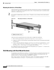
... the rack from Cisco. The kit part number is specific to ensure your safety: • This unit should be mounted at the bottom of the switch. Warning To prevent bodily injury when mounting or servicing this unit in a rack, you must take special precautions to the other Catalyst 2960 switches, see Chapter 2, "Switch Installation (24- Chapter 3 Switch Installation (8-Port Switches) Installing the Switch Rack-Mounting...
... the rack from Cisco. The kit part number is specific to ensure your safety: • This unit should be mounted at the bottom of the switch. Warning To prevent bodily injury when mounting or servicing this unit in a rack, you must take special precautions to the other Catalyst 2960 switches, see Chapter 2, "Switch Installation (24- Chapter 3 Switch Installation (8-Port Switches) Installing the Switch Rack-Mounting...
Hardware Installation Guide
Page 70
... in Figure 3-9. For configuration instructions about using the CLI setup program, go to Appendix C, "Configuring the Switch with the switch. You can order a kit containing the 19-inch rack-mounting brackets and hardware from Cisco. and 48-Port Switches)." 3-16 Catalyst 2960 Switch Hardware Installation Guide OL-7075-09 Use either the 10-32 pan-head screws or the...
... in Figure 3-9. For configuration instructions about using the CLI setup program, go to Appendix C, "Configuring the Switch with the switch. You can order a kit containing the 19-inch rack-mounting brackets and hardware from Cisco. and 48-Port Switches)." 3-16 Catalyst 2960 Switch Hardware Installation Guide OL-7075-09 Use either the 10-32 pan-head screws or the...

Hardware Installation Guide
Page 105
... 1-22 to a power source C-4 mounting in a rack (8-port switches) 3-15 to 3-16 on a wall (24- Index G ground connection warning 2-4, 3-3 grounded equipment warning 2-3, 3-3 H HP OpenView 1-22 humidity, relative A-1 I installation assigning the IP address C-4 connecting to configure switch 2-21, 3-18 network configuration examples 1-1 noise, electrical 2-5, 3-4 no user-serviceable parts warning 2-4 O overheating warning 2-2, 3-1 Catalyst 2960 Switch Hardware Installation Guide IN...
... 1-22 to a power source C-4 mounting in a rack (8-port switches) 3-15 to 3-16 on a wall (24- Index G ground connection warning 2-4, 3-3 grounded equipment warning 2-3, 3-3 H HP OpenView 1-22 humidity, relative A-1 I installation assigning the IP address C-4 connecting to configure switch 2-21, 3-18 network configuration examples 1-1 noise, electrical 2-5, 3-4 no user-serviceable parts warning 2-4 O overheating warning 2-2, 3-1 Catalyst 2960 Switch Hardware Installation Guide IN...
Hardware Installation Guide
Page 106
... 4-1, C-4 running at power on 2-6, 3-5, 4-2 power connecting to 2-5, 3-5 connectors 1-19, 1-20 power on 2-5, 3-5 IN-4 Catalyst 2960 Switch Hardware Installation Guide power-on self test See POST Power over Ethernet See PoE Power over Ethernet See PoE power supply AC power outlet ...the Catalyst 2960PD-8TT-L switch 1-13 internal 1-20 RPS connector 1-20 power supply warning 2-3, 3-3 procedures connection 2-14 to 2-20 installation 2-6 to 2-14, 3-5 to 3-18 product disposal warning 2-3, 3-3 R rack-mounting 2-7 to 2-10, 3-15 to 3-16 rack-mounting warning 2-3, 2-6, 3-2, 3-15 read the wall-mounting ...
... 4-1, C-4 running at power on 2-6, 3-5, 4-2 power connecting to 2-5, 3-5 connectors 1-19, 1-20 power on 2-5, 3-5 IN-4 Catalyst 2960 Switch Hardware Installation Guide power-on self test See POST Power over Ethernet See PoE Power over Ethernet See PoE power supply AC power outlet ...the Catalyst 2960PD-8TT-L switch 1-13 internal 1-20 RPS connector 1-20 power supply warning 2-3, 3-3 procedures connection 2-14 to 2-20 installation 2-6 to 2-14, 3-5 to 3-18 product disposal warning 2-3, 3-3 R rack-mounting 2-7 to 2-10, 3-15 to 3-16 rack-mounting warning 2-3, 2-6, 3-2, 3-15 read the wall-mounting ...