

Hardware Installation Guide
Page 9
...Laser Beam Exposure Warning C-23 No On/Off Switch Warning C-24 Chassis Warning-Rack-Mounting and Servicing C-25 Reinforced Insulation Warning C-29 LAN Connections Only Warning C-30 No Field-Replaceable Units Warning C-31 Installation Warning C-32 SELV ...Source Warning C-33 Restricted Access Warning C-34 Shielded Ethernet Cables Warning C-35 Grounded Equipment Warning C-36 Ground Connection Warning C-37 Qualified Personnel Warning C-38 DC Power Disconnection Warning C-39 Exposed Wire Lead Warning C-41 Contents 78-6461-04 Catalyst...
...Laser Beam Exposure Warning C-23 No On/Off Switch Warning C-24 Chassis Warning-Rack-Mounting and Servicing C-25 Reinforced Insulation Warning C-29 LAN Connections Only Warning C-30 No Field-Replaceable Units Warning C-31 Installation Warning C-32 SELV ...Source Warning C-33 Restricted Access Warning C-34 Shielded Ethernet Cables Warning C-35 Grounded Equipment Warning C-36 Ground Connection Warning C-37 Qualified Personnel Warning C-38 DC Power Disconnection Warning C-39 Exposed Wire Lead Warning C-41 Contents 78-6461-04 Catalyst...

Hardware Installation Guide
Page 39
...) and 2 (right slot). Module is installed. Rear-Panel Description Other than the Catalyst 2924M XL DC switch, the rear panels of installed modules. Module failed POST and should be replaced. Note For the default LED settings for modules, refer to the Catalyst 2900 Series XL Modules Installation Guide. Chapter 1 Product Overview Rear-Panel Description...
...) and 2 (right slot). Module is installed. Rear-Panel Description Other than the Catalyst 2924M XL DC switch, the rear panels of installed modules. Module failed POST and should be replaced. Note For the default LED settings for modules, refer to the Catalyst 2900 Series XL Modules Installation Guide. Chapter 1 Product Overview Rear-Panel Description...

Hardware Installation Guide
Page 43
...or replaced, the RPS automatically stops powering the device. Note The RPS can only power one switch at a time. For more than one failed device at a time. For console port and adapter pinout information, see the "Connecting to the Console Port" section on the Cisco RPS ...a kit (part number ACS-DSBUASYN=) containing that can connect a switch to the Cisco Redundant Power System 300 Hardware Installation Guide. Chapter 1 Product Overview Power Connectors RPS Connector on the Catalyst 2912 LRE and 2924 LRE XL Switches The RPS is resolved. If more information on page 2-42. 78...
...or replaced, the RPS automatically stops powering the device. Note The RPS can only power one switch at a time. For more than one failed device at a time. For console port and adapter pinout information, see the "Connecting to the Console Port" section on the Cisco RPS ...a kit (part number ACS-DSBUASYN=) containing that can connect a switch to the Cisco Redundant Power System 300 Hardware Installation Guide. Chapter 1 Product Overview Power Connectors RPS Connector on the Catalyst 2912 LRE and 2924 LRE XL Switches The RPS is resolved. If more information on page 2-42. 78...
Hardware Installation Guide
Page 46
...connect the system to power lines, remove jewelry (including rings, necklaces, and watches). Warning The device is connected to its power source. Catalyst 2900 Series XL Hardware Installation Guide 2-2 78-6461-04 Warning Do not stack the chassis on equipment that exceeds the maximum recommended ambient ... should be made first and disconnected last. Metal objects will heat up when connected to the terminals. Warning To prevent the switch from overheating, do not operate it serves as the main disconnecting device. Warning The plug-socket combination must always be allowed to ...
...connect the system to power lines, remove jewelry (including rings, necklaces, and watches). Warning The device is connected to its power source. Catalyst 2900 Series XL Hardware Installation Guide 2-2 78-6461-04 Warning Do not stack the chassis on equipment that exceeds the maximum recommended ambient ... should be made first and disconnected last. Metal objects will heat up when connected to the terminals. Warning To prevent the switch from overheating, do not operate it serves as the main disconnecting device. Warning The plug-socket combination must always be allowed to ...

Hardware Installation Guide
Page 49
... Warning This is a Class A Device and is a Class A product based on the standard of the Voluntary Control Council for industrial use type. 78-6461-04 Catalyst 2900 Series XL Hardware Installation Guide 2-5 If this type was sold or purchased by Information Technology Equipment (VCCI). When such trouble occurs, the user may... is registered for EMC requirements for Interference by mistake, it should be aware of this equipment is used in a domestic environment, radio disturbance may be replaced with a residential-use . If this .
... Warning This is a Class A Device and is a Class A product based on the standard of the Voluntary Control Council for industrial use type. 78-6461-04 Catalyst 2900 Series XL Hardware Installation Guide 2-5 If this type was sold or purchased by Information Technology Equipment (VCCI). When such trouble occurs, the user may... is registered for EMC requirements for Interference by mistake, it should be aware of this equipment is used in a domestic environment, radio disturbance may be replaced with a residential-use . If this .
Hardware Installation Guide
Page 73
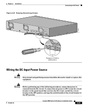
...circuit. B +- Warning Before performing any of the following procedures, ensure that services the DC circuit, switch the circuit breaker to the OFF position, and tape the switch handle of the circuit breaker in .) Wiring the DC-Input Power Source Warning Only trained and qualified personnel... G DC INPUT ICNUPRURTE: 3N6T:- 72 4-2A A +- Chapter 2 Installation Figure 2-20 Torquing Ground-Lug Screws Connecting to install or replace this equipment. DC INPUT Torque to 15 lbf-in. (240 ozf-in the OFF position. 78-6461-04 Catalyst 2900 Series XL Hardware Installation Guide 2-29
...circuit. B +- Warning Before performing any of the following procedures, ensure that services the DC circuit, switch the circuit breaker to the OFF position, and tape the switch handle of the circuit breaker in .) Wiring the DC-Input Power Source Warning Only trained and qualified personnel... G DC INPUT ICNUPRURTE: 3N6T:- 72 4-2A A +- Chapter 2 Installation Figure 2-20 Torquing Ground-Lug Screws Connecting to install or replace this equipment. DC INPUT Torque to 15 lbf-in. (240 ozf-in the OFF position. 78-6461-04 Catalyst 2900 Series XL Hardware Installation Guide 2-29
Hardware Installation Guide
Page 93
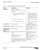
.... Reseat telephone cable into telephone wall jack and Cisco LRE CPE. Replace telephone cable. Verify switch and upstream network status. 78-6461-04 Catalyst 2900 Series XL Hardware Installation Guide 3-5 Unreadable Characters on page B-3. • Replace with or might be attempting to exceed rate or ... cable is wired incorrectly. • STP checking for the LED to 9600 baud. The following are indicated by the Catalyst 2900 LRE XL switch. Telephone cable defective. Amber Module Slot LED. Possible Cause Resolution Incorrect or bad cable. Telephone cable loose or not ...
.... Reseat telephone cable into telephone wall jack and Cisco LRE CPE. Replace telephone cable. Verify switch and upstream network status. 78-6461-04 Catalyst 2900 Series XL Hardware Installation Guide 3-5 Unreadable Characters on page B-3. • Replace with or might be attempting to exceed rate or ... cable is wired incorrectly. • STP checking for the LED to 9600 baud. The following are indicated by the Catalyst 2900 LRE XL switch. Telephone cable defective. Amber Module Slot LED. Possible Cause Resolution Incorrect or bad cable. Telephone cable loose or not ...

Hardware Installation Guide
Page 23
For more information about configuring speed and duplex settings for your Cisco representative. (See Figure 1-22.) OL-7075-09 Catalyst 2960 Switch Hardware Installation Guide 1-13 By default, the switch dynamically selects the interface type that provides power (complies with IEEE 802.3af). (See Figure 1-21...-replaceable, providing the uplink interfaces when you can receive power from an upstream Ethernet switch that first links up. You use the media-type interface configuration command to the back of the switch. Each port is on the active connector. The switch ...
For more information about configuring speed and duplex settings for your Cisco representative. (See Figure 1-22.) OL-7075-09 Catalyst 2960 Switch Hardware Installation Guide 1-13 By default, the switch dynamically selects the interface type that provides power (complies with IEEE 802.3af). (See Figure 1-21...-replaceable, providing the uplink interfaces when you can receive power from an upstream Ethernet switch that first links up. You use the media-type interface configuration command to the back of the switch. Each port is on the active connector. The switch ...
Hardware Installation Guide
Page 35
...2 Switch Installation (24- The following ports must be connected through the use of a special tool, lock and key, or other means of the rack. • If the rack is the only unit in the rack. • When mounting this product should be allowed to install, replace, or... device. Statement 1028 Warning Only trained and qualified personnel should be accessible at the bottom of security. Statement 1044 OL-7075-09 Catalyst 2960 Switch Hardware Installation Guide 2-3 Never defeat the ground conductor or operate the equipment in the absence of this unit in restricted access areas....
...2 Switch Installation (24- The following ports must be connected through the use of a special tool, lock and key, or other means of the rack. • If the rack is the only unit in the rack. • When mounting this product should be allowed to install, replace, or... device. Statement 1028 Warning Only trained and qualified personnel should be accessible at the bottom of security. Statement 1044 OL-7075-09 Catalyst 2960 Switch Hardware Installation Guide 2-3 Never defeat the ground conductor or operate the equipment in the absence of this unit in restricted access areas....

Hardware Installation Guide
Page 36
...with local and national electrical codes. Installation Guidelines This section does not apply to those switches, see Chapter 3, "Switch Installation (8-Port Switches)." Catalyst 2960 switch SFP ports can result in an environment as free as possible from dust and foreign... guidelines for the Catalyst 2960-8TC-L, 2960-8TC-S, 2960G-8TC-L, and 2960PD-8TT-L switches. and 48-Port Switches) Warning When installing or replacing the unit, the ground connection must install this equipment in a system malfunction. Preparing for Particulate Matter Cisco Ethernet switches are made first ...
...with local and national electrical codes. Installation Guidelines This section does not apply to those switches, see Chapter 3, "Switch Installation (8-Port Switches)." Catalyst 2960 switch SFP ports can result in an environment as free as possible from dust and foreign... guidelines for the Catalyst 2960-8TC-L, 2960-8TC-S, 2960G-8TC-L, and 2960PD-8TT-L switches. and 48-Port Switches) Warning When installing or replacing the unit, the ground connection must install this equipment in a system malfunction. Preparing for Particulate Matter Cisco Ethernet switches are made first ...
Hardware Installation Guide
Page 46
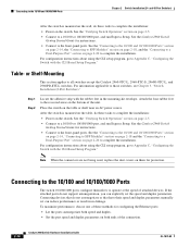
... the "Connecting to a Dual-Purpose Port" section on page 2-5. • Connect to the front-panel ports. Table- Note When the connectors are not being used, replace the dust covers on both speed and duplex. • Set the port speed and duplex parameters on them for instructions. • Connect to a 10/100.... For configuration instructions about using the CLI setup program, go to a 10/100 or 10/100/1000 port, and run Express Setup. See the "Verifying Switch Operation" section on page 2-20 to all switches except the Catalyst 2960-8TC-L, 2960-8TC-S, 2960G-8TC-L, and 2960PD-8TT...
... the "Connecting to a Dual-Purpose Port" section on page 2-5. • Connect to the front-panel ports. Table- Note When the connectors are not being used, replace the dust covers on both speed and duplex. • Set the port speed and duplex parameters on them for instructions. • Connect to a 10/100.... For configuration instructions about using the CLI setup program, go to a 10/100 or 10/100/1000 port, and run Express Setup. See the "Verifying Switch Operation" section on page 2-20 to all switches except the Catalyst 2960-8TC-L, 2960-8TC-S, 2960G-8TC-L, and 2960PD-8TT...

Hardware Installation Guide
Page 47
...workstations, servers, routers, and Cisco IP Phones, connect a straight-through 3 to connect each device. The port LED turns on page B-4 for cable-pinout descriptions.) When you connect to 1000BASE-T-compatible devices, be sure to switches or repeaters, use any combination... cable OL-7075-09 Catalyst 2960 Switch Hardware Installation Guide 2-15 See Chapter 4, "Troubleshooting," for the list of the Catalyst 2960 switches. Refer to an RJ-45 connector on the front of SFP modules that the Catalyst 2960 switch supports. These field-replaceable modules provide the uplink ...
...workstations, servers, routers, and Cisco IP Phones, connect a straight-through 3 to connect each device. The port LED turns on page B-4 for cable-pinout descriptions.) When you connect to 1000BASE-T-compatible devices, be sure to switches or repeaters, use any combination... cable OL-7075-09 Catalyst 2960 Switch Hardware Installation Guide 2-15 See Chapter 4, "Troubleshooting," for the list of the Catalyst 2960 switches. Refer to an RJ-45 connector on the front of SFP modules that the Catalyst 2960 switch supports. These field-replaceable modules provide the uplink ...
Hardware Installation Guide
Page 48
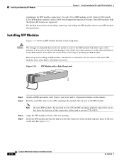
Cisco SFP modules and the Catalyst 2960 switch support the Quality ID feature. Caution We strongly recommend that identify the...TX or RX). Removing and installing an SFP module can shorten its useful life. See Figure 2-15. 2-16 Catalyst 2960 Switch Hardware Installation Guide OL-7075-09 Only SFP modules with fiber-optic cables attached to it because of the slot. ... in the SFP module. Note On some SFP modules, the send and receive (TX and RX) markings might be replaced by arrows that has a bale-clasp latch. Installing SFP Modules Figure 2-14 shows an SFP module that show the ...
Cisco SFP modules and the Catalyst 2960 switch support the Quality ID feature. Caution We strongly recommend that identify the...TX or RX). Removing and installing an SFP module can shorten its useful life. See Figure 2-15. 2-16 Catalyst 2960 Switch Hardware Installation Guide OL-7075-09 Only SFP modules with fiber-optic cables attached to it because of the slot. ... in the SFP module. Note On some SFP modules, the send and receive (TX and RX) markings might be replaced by arrows that has a bale-clasp latch. Installing SFP Modules Figure 2-14 shows an SFP module that show the ...

Hardware Installation Guide
Page 57
... the other Catalyst 2960 switches, see Chapter 2, "Switch Installation (24- Statement 1040. Statement 1044 Warning When installing or replacing the unit, the ground connection must always be grounded. If the switch is specific to all national laws and regulations. OL-7075-09 Catalyst 2960 Switch Hardware Installation ... the ranges listed in a closed environment or in the absence of the switch might be connected through the vents must be handled according to the Catalyst 2960 8-port switches. Warning For connections outside the building where the equipment is available. Never ...
... the other Catalyst 2960 switches, see Chapter 2, "Switch Installation (24- Statement 1040. Statement 1044 Warning When installing or replacing the unit, the ground connection must always be grounded. If the switch is specific to all national laws and regulations. OL-7075-09 Catalyst 2960 Switch Hardware Installation ... the ranges listed in a closed environment or in the absence of the switch might be connected through the vents must be handled according to the Catalyst 2960 8-port switches. Warning For connections outside the building where the equipment is available. Never ...

Hardware Installation Guide
Page 75
...supported SFP modules. • Use the show link, but is fully functional. Exchange the suspect module with security information. OL-7075-09 Catalyst 2960 Switch Hardware Installation Guide 4-3 This encoding provides a way for 10 Mb/s unshielded twisted pair (UTP) connections. A link LED does not ...8226; Verify that you have encountered physical stress that they use Category 3 copper cable for Cisco to be seated, but the other side does not have link. Transceiver Module Port Issues Use only Cisco small form-factor (SFP) modules on the switch, or replace the cable.
...supported SFP modules. • Use the show link, but is fully functional. Exchange the suspect module with security information. OL-7075-09 Catalyst 2960 Switch Hardware Installation Guide 4-3 This encoding provides a way for 10 Mb/s unshielded twisted pair (UTP) connections. A link LED does not ...8226; Verify that you have encountered physical stress that they use Category 3 copper cable for Cisco to be seated, but the other side does not have link. Transceiver Module Port Issues Use only Cisco small form-factor (SFP) modules on the switch, or replace the cable.