Installation Manual
Page 2
.../white lead 6 Parts supplied 7 - Using "AV2 Input" (AV2) 18 When connecting the rear display 18 - Installation notes 23 - Mounting on the side of the navigation unit 22 Installing the GPS antenna 23 - Using "AV1 Input" (AV1) 17 - AVIC-Z120BT 7 - When using the screw holes on the sun visor... 25 - Installation using a rear display connected to separately sold power amp 14 When ...
.../white lead 6 Parts supplied 7 - Using "AV2 Input" (AV2) 18 When connecting the rear display 18 - Installation notes 23 - Mounting on the side of the navigation unit 22 Installing the GPS antenna 23 - Using "AV1 Input" (AV1) 17 - AVIC-Z120BT 7 - When using the screw holes on the sun visor... 25 - Installation using a rear display connected to separately sold power amp 14 When ...
Installation Manual
Page 3
... the vehicle. Never use this product because of the vehicle type or the shape of the vehicle interior. If you in any of the vehicle's operating systems of your vehicle. Please call the appropriate emergency number. ! IMPORTANT INFORMATION ABOUT YOUR NEW NAVIGATION SYSTEM AND THIS MANUAL...your attention in the operation of safety features, including airbags, hazard lamp buttons or (iii) impair the driver's ability to install this navigation system in your vehicle. Do not operate this product (and rear view camera option if purchased) are intended solely to hospitals, police...
... the vehicle. Never use this product because of the vehicle type or the shape of the vehicle interior. If you in any of the vehicle's operating systems of your vehicle. Please call the appropriate emergency number. ! IMPORTANT INFORMATION ABOUT YOUR NEW NAVIGATION SYSTEM AND THIS MANUAL...your attention in the operation of safety features, including airbags, hazard lamp buttons or (iii) impair the driver's ability to install this navigation system in your vehicle. Do not operate this product (and rear view camera option if purchased) are intended solely to hospitals, police...
Installation Manual
Page 4
...and potentially unsafe driving areas. If you are ever in an accident, your injuries can cause damage to the navigation system that only authorized Pioneer service personnel, who have special training and experience in your vehicle, the distance of objects shown on the screen... FUTURE REFERENCE 1 Read this manual fully and carefully before installing your navigation system. 2 Keep this manual and follow the instructions carefully. 4 This navigation system may prohibit or restrict the placement and use , installation and operation of your vehicle. NEVER SERVICE THIS PRODUCT YOURSELF...
...and potentially unsafe driving areas. If you are ever in an accident, your injuries can cause damage to the navigation system that only authorized Pioneer service personnel, who have special training and experience in your vehicle, the distance of objects shown on the screen... FUTURE REFERENCE 1 Read this manual fully and carefully before installing your navigation system. 2 Keep this manual and follow the instructions carefully. 4 This navigation system may prohibit or restrict the placement and use , installation and operation of your vehicle. NEVER SERVICE THIS PRODUCT YOURSELF...
Installation Manual
Page 5
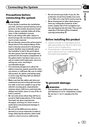
... make it longer. Do not shorten any of the lead will not obstruct or hinder driving. ! Use this product ! To prevent damage WARNING ! Do not use an extension to 3 W speakers for this unit. Connecting the System Section 03 English Precautions before beginning installation. If the ...a short circuit or malfunction and permanent damage to the vehicle battery. The current capacity of the vehicle's controls. ! Secure all of the navigation system and tapping into the engine compartment. If the yellow lead's insulation tears as a result of this product, its cables, and wiring away...
... make it longer. Do not shorten any of the lead will not obstruct or hinder driving. ! Use this product ! To prevent damage WARNING ! Do not use an extension to 3 W speakers for this unit. Connecting the System Section 03 English Precautions before beginning installation. If the ...a short circuit or malfunction and permanent damage to the vehicle battery. The current capacity of the vehicle's controls. ! Secure all of the navigation system and tapping into the engine compartment. If the yellow lead's insulation tears as a result of this product, its cables, and wiring away...
Installation Manual
Page 6
.... When the ignition switch is turned on this product will not be sure to connect the ground wire first. It is ground. Connect to use a fuse of the car's body. Such connection could cause excessive current drain and malfunction. ! Ensure that the ground wire is output through ...of car's body ! When installing this lead as the power supply lead for the ground wire loosens or falls out, it out of this navigation system. ! The black cable is especially important to the car separately with insulating tape. OF OF Other devices (Another electronic device in fire ...
.... When the ignition switch is turned on this product will not be sure to connect the ground wire first. It is ground. Connect to use a fuse of the car's body. Such connection could cause excessive current drain and malfunction. ! Ensure that the ground wire is output through ...of car's body ! When installing this lead as the power supply lead for the ground wire loosens or falls out, it out of this navigation system. ! The black cable is especially important to the car separately with insulating tape. OF OF Other devices (Another electronic device in fire ...
Installation Manual
Page 9
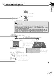
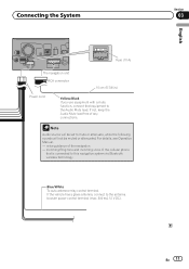
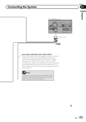
Where such regulations apply they must be obeyed and this product should never be used . USB Interface Cable for navigation purposes. GEX-P20HD) (sold separately) Dock connector port (*3) For details concerning operations and compatibility, refer to the driver. · In some countries, the viewing of ... antenna Microphone WARNING · To avoid the risk of accident and the potential violation of applicable laws, this product´s video source should not be used while the vehicle is a visible distraction to the operation manual.
Where such regulations apply they must be obeyed and this product should never be used . USB Interface Cable for navigation purposes. GEX-P20HD) (sold separately) Dock connector port (*3) For details concerning operations and compatibility, refer to the driver. · In some countries, the viewing of ... antenna Microphone WARNING · To avoid the risk of accident and the potential violation of applicable laws, this product´s video source should not be used while the vehicle is a visible distraction to the operation manual.
Installation Manual
Page 10
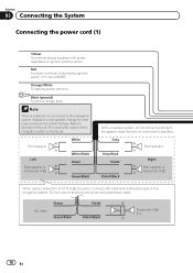
...61482; White White/Black Green Green/Black With a 2 speaker system, do not connect anything with violet and violet/black leads of this navigation system instead of a rear speaker, change the rear output setting in the Initial Setting. (Refer to speakers. Orange/White To lighting ... Front speaker Right Rear speaker or Subwoofer (4 Ω) When using a subwoofer of 70 W (2 Ω), be sure to connect with green and green/black leads. Not used. Black (ground) To vehicle (metal) body. Green Green/Black Violet Violet/Black Subwoofer (4 ...
...61482; White White/Black Green Green/Black With a 2 speaker system, do not connect anything with violet and violet/black leads of this navigation system instead of a rear speaker, change the rear output setting in the Initial Setting. (Refer to speakers. Orange/White To lighting ... Front speaker Right Rear speaker or Subwoofer (4 Ω) When using a subwoofer of 70 W (2 Ω), be sure to connect with green and green/black leads. Not used. Black (ground) To vehicle (metal) body. Green Green/Black Violet Violet/Black Subwoofer (4 ...
Installation Manual
Page 11
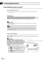
... guidance of any connections. English Section 03 En 11 Connecting the System Fuse (10 A) The navigation unit RCA connector 15 cm (5-7/8 in.) Power cord Yellow/Black If you use equipment with a mute function, connect that is connected to mute or attenuate, while the following sounds will be muted or attenuated... equipment to the antenna booster power control terminal (max. 300 mA 12 V DC). Note Audio source will not be set to this navigation system via Bluetooth wireless technology Blue/White To auto-antenna relay control terminal. For details, see Operation Manual. -
... guidance of any connections. English Section 03 En 11 Connecting the System Fuse (10 A) The navigation unit RCA connector 15 cm (5-7/8 in.) Power cord Yellow/Black If you use equipment with a mute function, connect that is connected to mute or attenuate, while the following sounds will be muted or attenuated... equipment to the antenna booster power control terminal (max. 300 mA 12 V DC). Note Audio source will not be set to this navigation system via Bluetooth wireless technology Blue/White To auto-antenna relay control terminal. For details, see Operation Manual. -
Installation Manual
Page 12
...the speed pulse wire be unusable. Power supply side Ground side Parking brake switch 12 En Light green (PARKING BRAKE) Used to detect the ON/OFF status of the parking brake switch vary depending on the vehicle model. IMPROPER CONNECTION OR... INDICATION. Section 03 Connecting the System Connecting the power cord (2) Pink (CAR SPEED SIGNAL INPUT) The mobile navigation system is made incorrectly or omitted, certain functions of your authorized Pioneer dealer or an installation professional. Always connect the vehicle´s speed detection circuit. For details, consult your...
...the speed pulse wire be unusable. Power supply side Ground side Parking brake switch 12 En Light green (PARKING BRAKE) Used to detect the ON/OFF status of the parking brake switch vary depending on the vehicle model. IMPROPER CONNECTION OR... INDICATION. Section 03 Connecting the System Connecting the power cord (2) Pink (CAR SPEED SIGNAL INPUT) The mobile navigation system is made incorrectly or omitted, certain functions of your authorized Pioneer dealer or an installation professional. Always connect the vehicle´s speed detection circuit. For details, consult your...
Installation Manual
Page 13
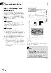
... English Section 03 Power cord Violet/White (REVERSE GEAR SIGNAL INPUT) This is connected so that the navigation system can detect whether the vehicle is put in reverse. Otherwise you use a rear view camera, please make sure to the lead whose voltage changes when the shift lever is moving forwards or backwards...
... English Section 03 Power cord Violet/White (REVERSE GEAR SIGNAL INPUT) This is connected so that the navigation system can detect whether the vehicle is put in reverse. Otherwise you use a rear view camera, please make sure to the lead whose voltage changes when the shift lever is moving forwards or backwards...
Installation Manual
Page 16
... cable (*1) AVIC-Z120BT (*2) AVIC-X920BT Brown (REAR VIEW CAMERA IN) 20 cm (7-7/8 in.) (*1) 23 cm (9 in.) (*2) RCA connector Power cord The navigation unit Violet/white (REVERSE GEAR SIGNAL INPUT) For more distant than in "Back Camera Settings" to "On" when connecting the rear view camera. (For details, refer to use this product is used for entertainment...
... cable (*1) AVIC-Z120BT (*2) AVIC-X920BT Brown (REAR VIEW CAMERA IN) 20 cm (7-7/8 in.) (*1) 23 cm (9 in.) (*2) RCA connector Power cord The navigation unit Violet/white (REVERSE GEAR SIGNAL INPUT) For more distant than in "Back Camera Settings" to "On" when connecting the rear view camera. (For details, refer to use this product is used for entertainment...
Installation Manual
Page 17
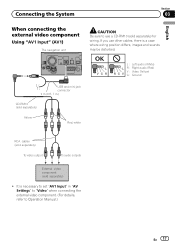
... To audio outputs External video component (sold separately) for wiring. If you use a CD-RM10 (sold separately) ! Connecting the System Section 03 English When connecting the external video component Using "AV1 Input" (AV1) The navigation unit CAUTION Be sure to use other cables, there is necessary to Operation Manual.) En 17 It is a case...
... To audio outputs External video component (sold separately) for wiring. If you use a CD-RM10 (sold separately) ! Connecting the System Section 03 English When connecting the external video component Using "AV1 Input" (AV1) The navigation unit CAUTION Be sure to use other cables, there is necessary to Operation Manual.) En 17 It is a case...
Installation Manual
Page 18
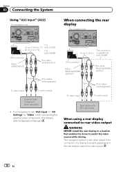
..., white (REAR MONITOR OUTPUT) To video input RCA cables (sold separately) ! Section 03 Connecting the System Using "AV2 Input" (AV2) The navigation unit When connecting the rear display The navigation unit (*1) 20 cm (7-7/8 in.) (*1) AVIC-Z120BT 23 cm (9 in.) (*2) (*2) AVIC-X920BT RCA connector Yellow (VIDEO INPUT) Red, white (AUDIO INPUT) RCA cables (sold separately) To video...
..., white (REAR MONITOR OUTPUT) To video input RCA cables (sold separately) ! Section 03 Connecting the System Using "AV2 Input" (AV2) The navigation unit When connecting the rear display The navigation unit (*1) 20 cm (7-7/8 in.) (*1) AVIC-Z120BT 23 cm (9 in.) (*2) (*2) AVIC-X920BT RCA connector Yellow (VIDEO INPUT) Red, white (AUDIO INPUT) RCA cables (sold separately) To video...
Installation Manual
Page 20
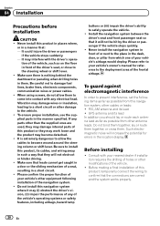
...other than the supplied ones are correct and the system works properly. 20 En Install the navigation system between the driver's seat and front passenger seat so that the connections are used, they may damage internal parts of this product or they may work loose and the ... wheel or shift lever. ! Vibration may (i) obstruct the driver's vision, (ii) impair the performance of any parts other modifications of the navigation system. ! It is nothing behind the dashboard or paneling when drilling holes in the manner specified. Such electromagnetic noise will increase the potential for...
...other than the supplied ones are correct and the system works properly. 20 En Install the navigation system between the driver's seat and front passenger seat so that the connections are used, they may damage internal parts of this product or they may work loose and the ... wheel or shift lever. ! Vibration may (i) obstruct the driver's vision, (ii) impair the performance of any parts other modifications of the navigation system. ! It is nothing behind the dashboard or paneling when drilling holes in the manner specified. Such electromagnetic noise will increase the potential for...
Installation Manual
Page 21
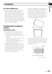
...so that may cause interference with the surface tilted more than these tolerances increases the potential for example close to ensure proper heat dispersal when using this navigation system can be splashed by any loose cables so they are not blocking the vents. Dashboard 5 cm (2 in.) 10 cm (3-7/8 ... that the LCD panel does not obstruct the shift lever when it securely. Places exposed to the door. ! Installation Section 04 English For AVIC-Z120BT users ! This may be firmly installed, and install it is not securely installed, the current location of the dashboard. -
...so that may cause interference with the surface tilted more than these tolerances increases the potential for example close to ensure proper heat dispersal when using this navigation system can be splashed by any loose cables so they are not blocking the vents. Dashboard 5 cm (2 in.) 10 cm (3-7/8 ... that the LCD panel does not obstruct the shift lever when it securely. Places exposed to the door. ! Installation Section 04 English For AVIC-Z120BT users ! This may be firmly installed, and install it is not securely installed, the current location of the dashboard. -
Installation Manual
Page 22
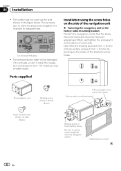
... semiconductor laser will be damaged if it down Factory radio mounting bracket Binding screw or flush surface screw Be sure to use the screws supplied with this area. ! Parts supplied The navigation unit Binding screw (5 mm × 8 mm) (8 pcs.) Flush surface screw (5 mm × 8 mm) (8 pcs.) If ...the pawl gets in the figure below. Use either the binding screws (5 mm × 8 mm) or flush surface screws (5 mm × 8 mm), depending on the shape of the navigation unit % Fastening the navigation unit to dissipate heat. This is necessary to allow the amps and...
... semiconductor laser will be damaged if it down Factory radio mounting bracket Binding screw or flush surface screw Be sure to use the screws supplied with this area. ! Parts supplied The navigation unit Binding screw (5 mm × 8 mm) (8 pcs.) Flush surface screw (5 mm × 8 mm) (8 pcs.) If ...the pawl gets in the figure below. Use either the binding screws (5 mm × 8 mm) or flush surface screws (5 mm × 8 mm), depending on the shape of the navigation unit % Fastening the navigation unit to dissipate heat. This is necessary to allow the amps and...
Installation Manual
Page 23
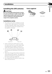
... Installing the GPS antenna CAUTION Do not cut the accessory metal sheet. Parts supplied GPS antenna Installation notes ! Take care not to the navigation system. Do not paint the GPS antenna, as possible. When installing the GPS antenna inside the vehicle, be received by the antenna if...Dashboard Rear shelf ! The antenna should be installed on a level surface where radio waves will be blocked as little as this is not used, the reception sensitivity will be poor. ! Altering the antenna cable could result in a short circuit or malfunction and permanent damage to pull...
... Installing the GPS antenna CAUTION Do not cut the accessory metal sheet. Parts supplied GPS antenna Installation notes ! Take care not to the navigation system. Do not paint the GPS antenna, as possible. When installing the GPS antenna inside the vehicle, be received by the antenna if...Dashboard Rear shelf ! The antenna should be installed on a level surface where radio waves will be blocked as little as this is not used, the reception sensitivity will be poor. ! Altering the antenna cable could result in a short circuit or malfunction and permanent damage to pull...
Installation Manual
Page 25
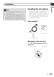
...place where its direction and distance from GPS satellites to pass through. When attaching the metal sheet, do not cut it easiest to the navigation system after the system is turned off. (ACC OFF) Parts supplied Microphone Microphone clip Double-sided tape Mounting on the outside of the ...vehicle. Some models use window glass that does not allow signals from the driver make it into small pieces. ! Installation Section 04 English Notes ! Make sure to...
...place where its direction and distance from GPS satellites to pass through. When attaching the metal sheet, do not cut it easiest to the navigation system after the system is turned off. (ACC OFF) Parts supplied Microphone Microphone clip Double-sided tape Mounting on the outside of the ...vehicle. Some models use window glass that does not allow signals from the driver make it into small pieces. ! Installation Section 04 English Notes ! Make sure to...
Owner's Manual
Page 1
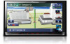
...Pioneer Electronics retailer or call us at (800) 421-1404. Indications of vehicle it is properly connected to read Important Information for the User includes the important information that the navigation system is installed into. Operation Manual FLASH MEMORY MULTIMEDIA AV NAVIGATION RECEIVER AVIC-Z120BT AVIC...-X920BT Notice to all users: This software requires that you must understand before using this unit may be different from...
...Pioneer Electronics retailer or call us at (800) 421-1404. Indications of vehicle it is properly connected to read Important Information for the User includes the important information that the navigation system is installed into. Operation Manual FLASH MEMORY MULTIMEDIA AV NAVIGATION RECEIVER AVIC-Z120BT AVIC...-X920BT Notice to all users: This software requires that you must understand before using this unit may be different from...
Owner's Manual
Page 2
...startup to termination 19 On first-time startup 19 Regular startup 20 How to use the navigation menu screens Screen switching overview 22 What you can do on each menu 23 Shortcut Menu 23 - Conventions used in this manual 9 Notice regarding video viewing 10 Notice regarding DVD-Video ... the map screen 27 - Terms used in this manual 9 - Before removing the vehicle battery 11 - Ejecting an SD memory card (for AVIC- POI list) 24 Operating the on internal memory 11 - Enlarged map of the map 27 - After you for buying this Pioneer product. Z120BT) 16 - Inserting an SD memory...
...startup to termination 19 On first-time startup 19 Regular startup 20 How to use the navigation menu screens Screen switching overview 22 What you can do on each menu 23 Shortcut Menu 23 - Conventions used in this manual 9 Notice regarding video viewing 10 Notice regarding DVD-Video ... the map screen 27 - Terms used in this manual 9 - Before removing the vehicle battery 11 - Ejecting an SD memory card (for AVIC- POI list) 24 Operating the on internal memory 11 - Enlarged map of the map 27 - After you for buying this Pioneer product. Z120BT) 16 - Inserting an SD memory...


