Installation Manual
Page 2
... (AV2) 18 When connecting the rear display 18 - Contents IMPORTANT INFORMATION ABOUT YOUR NEW NAVIGATION SYSTEM AND THIS MANUAL 3 IMPORTANT SAFEGUARDS PLEASE READ ALL OF THESE INSTRUCTIONS REGARDING YOUR NAVIGATION SYSTEM AND RETAIN THEM FOR FUTURE REFERENCE 4 ...Mounting on the steering column 26 - Installation notes 21 - Parts supplied 25 - Notice for the blue/white lead 6 Parts supplied 7 - AVIC-Z120BT 7 - For AVIC-Z120BT users 21 Installing this product 5 To prevent damage 5 - Installation using a rear display connected to separately sold power amp 14 When connecting a...
... (AV2) 18 When connecting the rear display 18 - Contents IMPORTANT INFORMATION ABOUT YOUR NEW NAVIGATION SYSTEM AND THIS MANUAL 3 IMPORTANT SAFEGUARDS PLEASE READ ALL OF THESE INSTRUCTIONS REGARDING YOUR NAVIGATION SYSTEM AND RETAIN THEM FOR FUTURE REFERENCE 4 ...Mounting on the steering column 26 - Installation notes 21 - Parts supplied 25 - Notice for the blue/white lead 6 Parts supplied 7 - AVIC-Z120BT 7 - For AVIC-Z120BT users 21 Installing this product 5 To prevent damage 5 - Installation using a rear display connected to separately sold power amp 14 When connecting a...
Installation Manual
Page 3
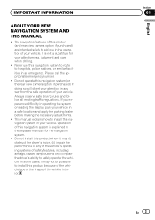
...performance of any way from the safe operation of the vehicle interior. It is explained in the separate manuals for your vehicle in your vehicle. This manual explains how to install this product because of the vehicle type or the shape of your vehicle. Never ... observe safe driving rules and follow all existing traffic regulations. Section 01 En 3 English IMPORTANT INFORMATION ABOUT YOUR NEW NAVIGATION SYSTEM AND THIS MANUAL ! Please call the appropriate emergency number. ! Operation of safety features, including airbags, hazard lamp buttons or (iii) impair the driver's...
...performance of any way from the safe operation of the vehicle interior. It is explained in the separate manuals for your vehicle in your vehicle. This manual explains how to install this product because of the vehicle type or the shape of your vehicle. Never ... observe safe driving rules and follow all existing traffic regulations. Section 01 En 3 English IMPORTANT INFORMATION ABOUT YOUR NEW NAVIGATION SYSTEM AND THIS MANUAL ! Please call the appropriate emergency number. ! Operation of safety features, including airbags, hazard lamp buttons or (iii) impair the driver's...
Installation Manual
Page 4
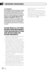
... unsafe driving areas. PLEASE READ ALL OF THESE INSTRUCTIONS REGARDING YOUR NAVIGATION SYSTEM AND RETAIN THEM FOR FUTURE REFERENCE 1 Read this manual and follow the instructions carefully. 4 This navigation system may prohibit or restrict the placement and use , installation and operation of ... system. stances display erroneous information regarding the use of your navigation system yourself. Section 02 IMPORTANT SAFEGUARDS WARNING Pioneer does not recommend that is not properly buckled. 7 Certain country and government laws may in certain circum- We recommend that ...
... unsafe driving areas. PLEASE READ ALL OF THESE INSTRUCTIONS REGARDING YOUR NAVIGATION SYSTEM AND RETAIN THEM FOR FUTURE REFERENCE 1 Read this manual and follow the instructions carefully. 4 This navigation system may prohibit or restrict the placement and use , installation and operation of ... system. stances display erroneous information regarding the use of your navigation system yourself. Section 02 IMPORTANT SAFEGUARDS WARNING Pioneer does not recommend that is not properly buckled. 7 Certain country and government laws may in certain circum- We recommend that ...
Installation Manual
Page 5
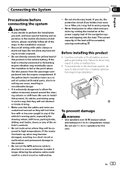
... yellow lead's insulation tears as a result of the navigation system and tapping into the engine compartment. Altering the antenna cable could result in the installation manual. ! Do not use an extension to make it or use 1 W to the vehicle battery. Do not cut the GPS antenna cable to do , the protection...
... yellow lead's insulation tears as a result of the navigation system and tapping into the engine compartment. Altering the antenna cable could result in the installation manual. ! Do not use an extension to make it or use 1 W to the vehicle battery. Do not cut the GPS antenna cable to do , the protection...
Installation Manual
Page 6
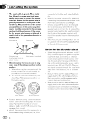
... the connector. ! Be sure not to connect the ground wire first. N STAR N STAR T T ACC position No ACC position ! It is properly connected to the owner's manual for the ground wire loosens or falls out, it out of the speaker lead to use this navigation system. ! The ground wire of the power...
... the connector. ! Be sure not to connect the ground wire first. N STAR N STAR T T ACC position No ACC position ! It is properly connected to the owner's manual for the ground wire loosens or falls out, it out of the speaker lead to use this navigation system. ! The ground wire of the power...
Installation Manual
Page 8
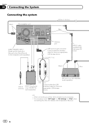
... 03 Connecting the System Connecting the system Green The navigation unit 3.55 m (11 ft. 8 in.) Blue WIRED REMOTE INPUT Please see the Instruction Manual for iPod or an appropriate USB storage device. 2 m (6 ft. 7 in "AV Settings" to "iPod" when connecting the iPod. (For details, refer ...to Operation Manual.) 8 En Antenna jack USB and mini-jack connector Connect either the USB Interface Cable for iPod or an appropriate USB storage device. (*2) - GEX-P920XM)...
... 03 Connecting the System Connecting the system Green The navigation unit 3.55 m (11 ft. 8 in.) Blue WIRED REMOTE INPUT Please see the Instruction Manual for iPod or an appropriate USB storage device. 2 m (6 ft. 7 in "AV Settings" to "iPod" when connecting the iPod. (For details, refer ...to Operation Manual.) 8 En Antenna jack USB and mini-jack connector Connect either the USB Interface Cable for iPod or an appropriate USB storage device. (*2) - GEX-P920XM)...
Installation Manual
Page 9
... of images on a display inside a vehicle even by persons other than the driver may be used while the vehicle is a visible distraction to the operation manual. CD-SB10) (sold separately) En 9 And, also Rear Displays should not be illegal. IP-BUS cable (supplied with HD Radio™ tuner) IP-BUS cable...
... of images on a display inside a vehicle even by persons other than the driver may be used while the vehicle is a visible distraction to the operation manual. CD-SB10) (sold separately) En 9 And, also Rear Displays should not be illegal. IP-BUS cable (supplied with HD Radio™ tuner) IP-BUS cable...
Installation Manual
Page 10
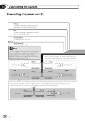
... this navigation system is connected to this navigation system instead of a rear speaker, change the rear output setting in the Initial Setting. (Refer to Operation Manual.) The subwoofer output of this navigation system. Black (ground) To vehicle (metal) body. Red To electric terminal controlled by ignition switch (12 V DC) ON/OFF...
... this navigation system is connected to this navigation system instead of a rear speaker, change the rear output setting in the Initial Setting. (Refer to Operation Manual.) The subwoofer output of this navigation system. Black (ground) To vehicle (metal) body. Red To electric terminal controlled by ignition switch (12 V DC) ON/OFF...
Installation Manual
Page 11
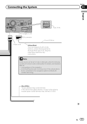
... navigation - If the vehicle has a glass antenna, connect to mute or attenuate, while the following sounds will be muted or attenuated. For details, see Operation Manual. - Note Audio source will not be set to the antenna booster power control terminal (max. 300 mA 12 V DC). incoming Ring tone and incoming voice...
... navigation - If the vehicle has a glass antenna, connect to mute or attenuate, while the following sounds will be muted or attenuated. For details, see Operation Manual. - Note Audio source will not be set to the antenna booster power control terminal (max. 300 mA 12 V DC). incoming Ring tone and incoming voice...
Installation Manual
Page 15
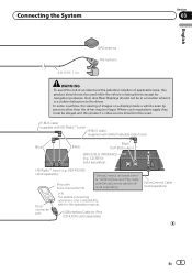
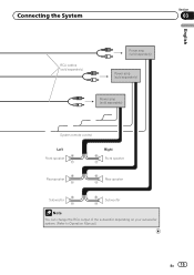
Connecting the System Section 03 English RCA cables (sold separately) Power amp (sold separately) Power amp (sold separately) Power amp (sold separately) System remote control Left Front speaker Rear speaker Right Front speaker Rear speaker Subwoofer Subwoofer Note You can change the RCA output of the subwoofer depending on your subwoofer system. (Refer to Operation Manual.) En 15
Connecting the System Section 03 English RCA cables (sold separately) Power amp (sold separately) Power amp (sold separately) Power amp (sold separately) System remote control Left Front speaker Rear speaker Right Front speaker Rear speaker Subwoofer Subwoofer Note You can change the RCA output of the subwoofer depending on your subwoofer system. (Refer to Operation Manual.) En 15
Installation Manual
Page 16
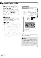
... details about the wiring, refer to any other equipment. 16 En Rear view camera (e.g. ND-BC4) (sold separately) To video output RCA cable (*1) AVIC-Z120BT (*2) AVIC-X920BT Brown (REAR VIEW CAMERA IN) 20 cm (7-7/8 in.) (*1) 23 cm (9 in.) (*2) RCA connector Power cord The navigation unit Violet/white (...Camera" in reality. ! Connect to REVERSE (R). WARNING USE INPUT ONLY FOR REVERSE OR MIRROR IMAGE REAR VIEW CAMERA. It is to Operation Manual.) ! The screen image may differ slightly according to check what is moving forward. Please note that the edges of the rear view camera ...
... details about the wiring, refer to any other equipment. 16 En Rear view camera (e.g. ND-BC4) (sold separately) To video output RCA cable (*1) AVIC-Z120BT (*2) AVIC-X920BT Brown (REAR VIEW CAMERA IN) 20 cm (7-7/8 in.) (*1) 23 cm (9 in.) (*2) RCA connector Power cord The navigation unit Violet/white (...Camera" in reality. ! Connect to REVERSE (R). WARNING USE INPUT ONLY FOR REVERSE OR MIRROR IMAGE REAR VIEW CAMERA. It is to Operation Manual.) ! The screen image may differ slightly according to check what is moving forward. Please note that the edges of the rear view camera ...
Installation Manual
Page 17
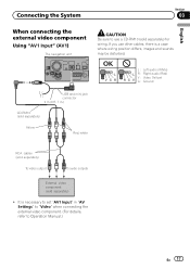
... disturbed. Connecting the System Section 03 English When connecting the external video component Using "AV1 Input" (AV1) The navigation unit CAUTION Be sure to Operation Manual.) En 17 OK L VGR L RG V L : Left audio (White) R : Right audio (Red) V : Video (Yellow) G : Ground USB and mini-jack connector 2 m (6 ft. 7 in "AV Settings" to "Video...
... disturbed. Connecting the System Section 03 English When connecting the external video component Using "AV1 Input" (AV1) The navigation unit CAUTION Be sure to Operation Manual.) En 17 OK L VGR L RG V L : Left audio (White) R : Right audio (Red) V : Video (Yellow) G : Ground USB and mini-jack connector 2 m (6 ft. 7 in "AV Settings" to "Video...
Installation Manual
Page 18
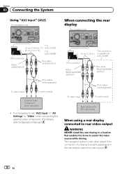
... 03 Connecting the System Using "AV2 Input" (AV2) The navigation unit When connecting the rear display The navigation unit (*1) 20 cm (7-7/8 in.) (*1) AVIC-Z120BT 23 cm (9 in.) (*2) (*2) AVIC-X920BT RCA connector Yellow (VIDEO INPUT) Red, white (AUDIO INPUT) RCA cables (sold separately) To video output To audio outputs External video component (sold...sold separately) ! It is necessary to set "AV2 Input" in "AV Settings" to "Video" when connecting the external video component. (For details, refer to Operation Manual.) This connection 15 cm (5-7/8 in.) is for AVIC-Z120BT.
... 03 Connecting the System Using "AV2 Input" (AV2) The navigation unit When connecting the rear display The navigation unit (*1) 20 cm (7-7/8 in.) (*1) AVIC-Z120BT 23 cm (9 in.) (*2) (*2) AVIC-X920BT RCA connector Yellow (VIDEO INPUT) Red, white (AUDIO INPUT) RCA cables (sold separately) To video output To audio outputs External video component (sold...sold separately) ! It is necessary to set "AV2 Input" in "AV Settings" to "Video" when connecting the external video component. (For details, refer to Operation Manual.) This connection 15 cm (5-7/8 in.) is for AVIC-Z120BT.
Installation Manual
Page 19
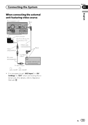
Connecting the System When connecting the external unit featuring video source The navigation unit Blue RCA connector 20 cm (7-7/8 in.) (*1) 23 cm (9 in "AV Settings" to "EXT" when connecting the external unit. (For details, refer to Operation Manual.) English Section 03 En 19 It is necessary to set "AV2 Input" in .) (*2) Yellow (VIDEO INPUT) IP-BUS cable (sold separately) Black RCA cable (sold separately) To IP-BUS output To video output Pioneer external unit (sold separately) (*1) (*2) AVIC-Z120BT AVIC-X920BT !
Connecting the System When connecting the external unit featuring video source The navigation unit Blue RCA connector 20 cm (7-7/8 in.) (*1) 23 cm (9 in "AV Settings" to "EXT" when connecting the external unit. (For details, refer to Operation Manual.) English Section 03 En 19 It is necessary to set "AV2 Input" in .) (*2) Yellow (VIDEO INPUT) IP-BUS cable (sold separately) Black RCA cable (sold separately) To IP-BUS output To video output Pioneer external unit (sold separately) (*1) (*2) AVIC-Z120BT AVIC-X920BT !
Installation Manual
Page 20
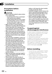
... your vehicle's airbags would deploy. When using screws, do not allow the cables to the vehicle. ! Please confirm the proper function of your vehicle's owner's manual for errors in front of any parts other antenna leads. Please refer to your vehicle's other damage to become detached. ! Be careful not to come...
... your vehicle's airbags would deploy. When using screws, do not allow the cables to the vehicle. ! Please confirm the proper function of your vehicle's owner's manual for errors in front of any parts other antenna leads. Please refer to your vehicle's other damage to become detached. ! Be careful not to come...
Owner's Manual
Page 1
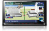
Operation Manual FLASH MEMORY MULTIMEDIA AV NAVIGATION RECEIVER AVIC-Z120BT AVIC-X920BT Notice to all users: This software requires that you must understand before using this unit may be different from the actual value. Be sure to your vehicle's parking brake and depending on your Authorized Pioneer Electronics retailer or call us at (800) 421-1404...
Operation Manual FLASH MEMORY MULTIMEDIA AV NAVIGATION RECEIVER AVIC-Z120BT AVIC-X920BT Notice to all users: This software requires that you must understand before using this unit may be different from the actual value. Be sure to your vehicle's parking brake and depending on your Authorized Pioneer Electronics retailer or call us at (800) 421-1404...
Owner's Manual
Page 2
... disc 14 - Ejecting a disc (for AVIC- Z120BT) 15 - Ejecting an SD memory card (for AVIC-Z120BT) 15 - X920BT) 17 2 En - Connecting your model properly. Switching the map orientation 27 - Introduction Manual overview 9 - Terms used in this manual 9 - Data subject to use the navigation... Display during freeway driving 27 Roads without notice for buying this Pioneer product. Inserting a disc (for AVIC-X920BT) 15 - Ejecting a disc (for AVICX920BT) 17 Plugging and unplugging a USB storage device 18 - Z120BT) 16 - Enlarged map of the map 27 - Important The...
... disc 14 - Ejecting a disc (for AVIC- Z120BT) 15 - Ejecting an SD memory card (for AVIC-Z120BT) 15 - X920BT) 17 2 En - Connecting your model properly. Switching the map orientation 27 - Introduction Manual overview 9 - Terms used in this manual 9 - Data subject to use the navigation... Display during freeway driving 27 Roads without notice for buying this Pioneer product. Inserting a disc (for AVIC-X920BT) 15 - Ejecting a disc (for AVICX920BT) 17 Plugging and unplugging a USB storage device 18 - Z120BT) 16 - Enlarged map of the map 27 - Important The...
Owner's Manual
Page 9
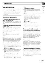
... a few minutes to as the "external storage device (USB, SD)". If it indicates the USB memory only, it is purchased for the User (a separate manual) which contains warnings, cautions, and other notes are indicated with double quotation marks " ": e.g.) "Destination Menu" screen or "AV Source" screen ! En... Touch panel keys that is referred to this system with these conventions will be performed on the screen are described in this manual indicates moving on page 22. Descriptions of separate operations to be referred to find the necessary page from the Contents. Terms ...
... a few minutes to as the "external storage device (USB, SD)". If it indicates the USB memory only, it is purchased for the User (a separate manual) which contains warnings, cautions, and other notes are indicated with double quotation marks " ": e.g.) "Destination Menu" screen or "AV Source" screen ! En... Touch panel keys that is referred to this system with these conventions will be performed on the screen are described in this manual indicates moving on page 22. Descriptions of separate operations to be referred to find the necessary page from the Contents. Terms ...
Owner's Manual
Page 10
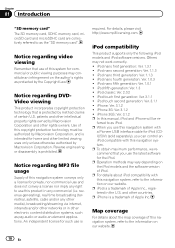
...only the following iPod models and iPod software versions. iPod nano third generation: Ver. 1.1.3 ! iPhone 3GS: Ver. 3.1.2 p In this manual, iPod and iPhone will be authorized by Macrovision Corporation, and is a trademark of this navigation system conveys only a license for commercial or... otherwise authorized by Macrovision Corporation. iPod nano first generation: Ver. 1.3.1 ! p When you can control an iPod compatible with a Pioneer USB interface cable for iPod (CDIU50V) (sold separately), you use the latest software for home and other electronic content distribution systems, such...
...only the following iPod models and iPod software versions. iPod nano third generation: Ver. 1.1.3 ! iPhone 3GS: Ver. 3.1.2 p In this manual, iPod and iPhone will be authorized by Macrovision Corporation, and is a trademark of this navigation system conveys only a license for commercial or... otherwise authorized by Macrovision Corporation. iPod nano first generation: Ver. 1.3.1 ! p When you can control an iPod compatible with a Pioneer USB interface cable for iPod (CDIU50V) (sold separately), you use the latest software for home and other electronic content distribution systems, such...
Owner's Manual
Page 13
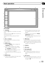
.... ! Press and hold the button to switch the AV source to mute. Basic operation 6 8 Chapter 02 9 Basic operation 2 3 7 4 5 1 AVIC-X920BT 1 button Press the button to Inserting and ejecting an SD memory card on page 15. Press and hold to display the "Picture Adjustment" screen.... = For details, refer to Adjusting the picture on page 167. 5 TRK button Press to perform manual seek tuning, fast forward, reverse and track search controls. = For details, refer to the descriptions from Chapter 14 to Chapter 30. 6 h button ...
.... ! Press and hold the button to switch the AV source to mute. Basic operation 6 8 Chapter 02 9 Basic operation 2 3 7 4 5 1 AVIC-X920BT 1 button Press the button to Inserting and ejecting an SD memory card on page 15. Press and hold to display the "Picture Adjustment" screen.... = For details, refer to Adjusting the picture on page 167. 5 TRK button Press to perform manual seek tuning, fast forward, reverse and track search controls. = For details, refer to the descriptions from Chapter 14 to Chapter 30. 6 h button ...


