Installation Manual
Page 3
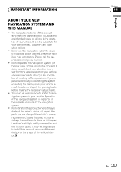
...) are intended solely to aid you experience difficulty in operating the system or reading the display, park your vehicle. Operation of the vehicle interior. Do not install this navigation system in your attention in the separate manuals for your vehicle. In some cases, it may not...location and apply the parking brake before making the necessary adjustments. ! This manual explains how to install this product because of the vehicle type or the shape of this navigation system to route to safely operate the vehicle. Section 01 En 3 English Never use this navigation system is...
...) are intended solely to aid you experience difficulty in operating the system or reading the display, park your vehicle. Operation of the vehicle interior. Do not install this navigation system in your attention in the separate manuals for your vehicle. In some cases, it may not...location and apply the parking brake before making the necessary adjustments. ! This manual explains how to install this product because of the vehicle type or the shape of this navigation system to route to safely operate the vehicle. Section 01 En 3 English Never use this navigation system is...
Installation Manual
Page 4
... that is not properly buckled. 7 Certain country and government laws may prohibit or restrict the placement and use , installation and operation of objects shown on the screen, and compass directions. Installing or servicing this product and its connecting cables may in mobile electronics..., set up and install this manual handy for future reference. 3 Pay close attention to the navigation system that only authorized Pioneer service personnel, who have special training and experience in certain circum- siderably more severe...
... that is not properly buckled. 7 Certain country and government laws may prohibit or restrict the placement and use , installation and operation of objects shown on the screen, and compass directions. Installing or servicing this product and its connecting cables may in mobile electronics..., set up and install this manual handy for future reference. 3 Pay close attention to the navigation system that only authorized Pioneer service personnel, who have special training and experience in certain circum- siderably more severe...
Installation Manual
Page 8
... USB Interface Cable for iPod or an appropriate USB storage device. 2 m (6 ft. 7 in "AV Settings" to "iPod" when connecting the iPod. (For details, refer to Operation Manual.) 8 En GEX-P920XM) (sold separately) (*1) Connect either the interface cable for iPod or an appropriate USB storage device. (*2) -
... USB Interface Cable for iPod or an appropriate USB storage device. 2 m (6 ft. 7 in "AV Settings" to "iPod" when connecting the iPod. (For details, refer to Operation Manual.) 8 En GEX-P920XM) (sold separately) (*1) Connect either the interface cable for iPod or an appropriate USB storage device. (*2) -
Installation Manual
Page 9
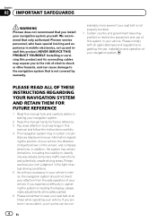
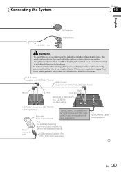
... viewing of images on a display inside a vehicle even by persons other than the driver may be used while the vehicle is a visible distraction to the operation manual. IP-BUS cable (supplied with HD Radio™ tuner) IP-BUS cable (supplied with SiriusConnect vehicle kit" (sold separately) HD Radio™ tuner (e.g. Connecting the...
... viewing of images on a display inside a vehicle even by persons other than the driver may be used while the vehicle is a visible distraction to the operation manual. IP-BUS cable (supplied with HD Radio™ tuner) IP-BUS cable (supplied with SiriusConnect vehicle kit" (sold separately) HD Radio™ tuner (e.g. Connecting the...
Installation Manual
Page 10
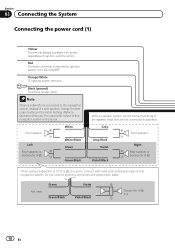
... of this navigation system is connected to this navigation system instead of a rear speaker, change the rear output setting in the Initial Setting. (Refer to Operation Manual.) The subwoofer output of this navigation system. Note When a subwoofer is monaural. Front speaker Left Rear speaker or Subwoofer (4 Ω) White...
... of this navigation system is connected to this navigation system instead of a rear speaker, change the rear output setting in the Initial Setting. (Refer to Operation Manual.) The subwoofer output of this navigation system. Note When a subwoofer is monaural. Front speaker Left Rear speaker or Subwoofer (4 Ω) White...
Installation Manual
Page 11
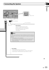
...-antenna relay control terminal. Note Audio source will be set to the antenna booster power control terminal (max. 300 mA 12 V DC). For details, see Operation Manual. - If not, keep the Audio Mute lead free of the navigation - incoming Ring tone and incoming voice of the cellular phone that equipment to the...
...-antenna relay control terminal. Note Audio source will be set to the antenna booster power control terminal (max. 300 mA 12 V DC). For details, see Operation Manual. - If not, keep the Audio Mute lead free of the navigation - incoming Ring tone and incoming voice of the cellular phone that equipment to the...
Installation Manual
Page 15
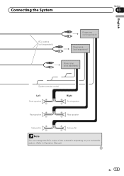
Connecting the System Section 03 English RCA cables (sold separately) Power amp (sold separately) Power amp (sold separately) Power amp (sold separately) System remote control Left Front speaker Rear speaker Right Front speaker Rear speaker Subwoofer Subwoofer Note You can change the RCA output of the subwoofer depending on your subwoofer system. (Refer to Operation Manual.) En 15
Connecting the System Section 03 English RCA cables (sold separately) Power amp (sold separately) Power amp (sold separately) Power amp (sold separately) System remote control Left Front speaker Rear speaker Right Front speaker Rear speaker Subwoofer Subwoofer Note You can change the RCA output of the subwoofer depending on your subwoofer system. (Refer to Operation Manual.) En 15
Installation Manual
Page 16
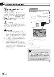
...Notes ! Rear view camera (e.g. WARNING USE INPUT ONLY FOR REVERSE OR MIRROR IMAGE REAR VIEW CAMERA. ND-BC4) (sold separately) To video output RCA cable (*1) AVIC-Z120BT (*2) AVIC-X920BT Brown (REAR VIEW CAMERA IN) 20 cm (7-7/8 in.) (*1) 23 cm (9 in "Back Camera Settings" to "On" when connecting the rear view camera...to check what is behind you while driving. Do not connect to the rear view camera. CAUTION ! The rear view camera function is to Operation Manual.) ! The object in rear view may appear reversed. ! Rear View mode also allows you to keep an eye on page 12. OTHER USE...
...Notes ! Rear view camera (e.g. WARNING USE INPUT ONLY FOR REVERSE OR MIRROR IMAGE REAR VIEW CAMERA. ND-BC4) (sold separately) To video output RCA cable (*1) AVIC-Z120BT (*2) AVIC-X920BT Brown (REAR VIEW CAMERA IN) 20 cm (7-7/8 in.) (*1) 23 cm (9 in "Back Camera Settings" to "On" when connecting the rear view camera...to check what is behind you while driving. Do not connect to the rear view camera. CAUTION ! The rear view camera function is to Operation Manual.) ! The object in rear view may appear reversed. ! Rear View mode also allows you to keep an eye on page 12. OTHER USE...
Installation Manual
Page 17
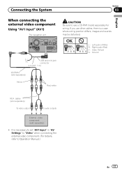
... English When connecting the external video component Using "AV1 Input" (AV1) The navigation unit CAUTION Be sure to use other cables, there is necessary to Operation Manual.) En 17 OK L VGR L RG V L : Left audio (White) R : Right audio (Red) V : Video (Yellow) G : Ground USB and mini-jack connector 2 m (6 ft. 7 in "AV Settings" to "Video...
... English When connecting the external video component Using "AV1 Input" (AV1) The navigation unit CAUTION Be sure to use other cables, there is necessary to Operation Manual.) En 17 OK L VGR L RG V L : Left audio (White) R : Right audio (Red) V : Video (Yellow) G : Ground USB and mini-jack connector 2 m (6 ft. 7 in "AV Settings" to "Video...
Installation Manual
Page 18
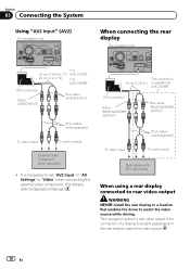
...is available for AVIC-Z120BT. This navigation system's rear video output is for connection of a display to enable passengers in .) is necessary to set "AV2 Input" in "AV Settings" to "Video" when connecting the external video component. (For details, refer to Operation Manual.) This connection... 15 cm (5-7/8 in the rear seats to rear video output WARNING NEVER install the rear display in .) (*2) (*2) AVIC-X920BT RCA connector Yellow (VIDEO INPUT) Red, white (AUDIO INPUT) RCA ...
...is available for AVIC-Z120BT. This navigation system's rear video output is for connection of a display to enable passengers in .) is necessary to set "AV2 Input" in "AV Settings" to "Video" when connecting the external video component. (For details, refer to Operation Manual.) This connection... 15 cm (5-7/8 in the rear seats to rear video output WARNING NEVER install the rear display in .) (*2) (*2) AVIC-X920BT RCA connector Yellow (VIDEO INPUT) Red, white (AUDIO INPUT) RCA ...
Installation Manual
Page 19
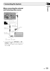
Connecting the System When connecting the external unit featuring video source The navigation unit Blue RCA connector 20 cm (7-7/8 in.) (*1) 23 cm (9 in "AV Settings" to "EXT" when connecting the external unit. (For details, refer to Operation Manual.) English Section 03 En 19 It is necessary to set "AV2 Input" in .) (*2) Yellow (VIDEO INPUT) IP-BUS cable (sold separately) Black RCA cable (sold separately) To IP-BUS output To video output Pioneer external unit (sold separately) (*1) (*2) AVIC-Z120BT AVIC-X920BT !
Connecting the System When connecting the external unit featuring video source The navigation unit Blue RCA connector 20 cm (7-7/8 in.) (*1) 23 cm (9 in "AV Settings" to "EXT" when connecting the external unit. (For details, refer to Operation Manual.) English Section 03 En 19 It is necessary to set "AV2 Input" in .) (*2) Yellow (VIDEO INPUT) IP-BUS cable (sold separately) Black RCA cable (sold separately) To IP-BUS output To video output Pioneer external unit (sold separately) (*1) (*2) AVIC-Z120BT AVIC-X920BT !
Installation Manual
Page 20
...allow the cables to confirm that : - Make sure that leads cannot get caught in front of the driver's seat, or close to safely operate the vehicle. ! FM, AM antenna and its lead In addition you should lay or route each antenna lead as far as on the floor ...(ii) impair the performance of any electrical lead. tion of your vehicle's owner's manual for errors in such a way that it may damage wires or insulation, leading to a short circuit or other modifications of the vehicle's operating systems or safety features, including airbags, hazard lamp buttons or (iii) impair the ...
...allow the cables to confirm that : - Make sure that leads cannot get caught in front of the driver's seat, or close to safely operate the vehicle. ! FM, AM antenna and its lead In addition you should lay or route each antenna lead as far as on the floor ...(ii) impair the performance of any electrical lead. tion of your vehicle's owner's manual for errors in such a way that it may damage wires or insulation, leading to a short circuit or other modifications of the vehicle's operating systems or safety features, including airbags, hazard lamp buttons or (iii) impair the ...
Owner's Manual
Page 1
... connected to your vehicle's parking brake and depending on your Authorized Pioneer Electronics retailer or call us at (800) 421-1404. English For more information, please contact your vehicle, additional installation may be required. Operation Manual FLASH MEMORY MULTIMEDIA AV NAVIGATION RECEIVER AVIC-Z120BT AVIC-X920BT Notice to all users: This software requires that you must...
... connected to your vehicle's parking brake and depending on your Authorized Pioneer Electronics retailer or call us at (800) 421-1404. English For more information, please contact your vehicle, additional installation may be required. Operation Manual FLASH MEMORY MULTIMEDIA AV NAVIGATION RECEIVER AVIC-Z120BT AVIC-X920BT Notice to all users: This software requires that you must...
Owner's Manual
Page 2
... how to operate your model properly. Please read the map screen 25 - Actual screens may differ from startup to termination 19 On first-time startup 19 Regular startup 20 How to the position you have finished reading the instructions, keep this manual in a safe place for future reference. Inserting a disc (for AVIC-Z120BT) 15...
... how to operate your model properly. Please read the map screen 25 - Actual screens may differ from startup to termination 19 On first-time startup 19 Regular startup 20 How to the position you have finished reading the instructions, keep this manual in a safe place for future reference. Inserting a disc (for AVIC-Z120BT) 15...
Owner's Manual
Page 9
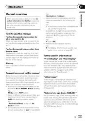
...the screen are described in bold in ALL CAPITAL, BOLD lettering: e.g.) MENU button, MAP button. ! En 9 How to use this manual Finding the operation procedure for use your navigation system are indicated with # at the end of DVD-Video, DivX®, iPod, and any equipment that ... on , take a few minutes to read Important Information for the User (a separate manual) which contains warnings, cautions, and other notes are described in this manual indicates moving images of the manual. Finding the operation procedure from a menu name If you want to do, you can find the page...
...the screen are described in bold in ALL CAPITAL, BOLD lettering: e.g.) MENU button, MAP button. ! En 9 How to use this manual Finding the operation procedure for use your navigation system are indicated with # at the end of DVD-Video, DivX®, iPod, and any equipment that ... on , take a few minutes to read Important Information for the User (a separate manual) which contains warnings, cautions, and other notes are described in this manual indicates moving images of the manual. Finding the operation procedure from a menu name If you want to do, you can find the page...
Owner's Manual
Page 86
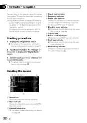
... to Switching the recep- Otherwise, "A" appears. 7 Blending mode indicator = For details, refer to the HD Radio tuner's operation manual. a Seek type indicator = For details, refer to Switching the display on page 88. 86 En If a digital broadcasting is tuned to: FM1, FM2,...touch panel keys on the screen to control the radio. = For details, refer to the radio by using the navigation system. This section describes operations for HD Radio reception. b Multicasting indicator Shows the number of multicast channels in the current frequency. Chapter 16 HD Radioä reception You ...
... to Switching the recep- Otherwise, "A" appears. 7 Blending mode indicator = For details, refer to the HD Radio tuner's operation manual. a Seek type indicator = For details, refer to Switching the display on page 88. 86 En If a digital broadcasting is tuned to: FM1, FM2,...touch panel keys on the screen to control the radio. = For details, refer to the radio by using the navigation system. This section describes operations for HD Radio reception. b Multicasting indicator Shows the number of multicast channels in the current frequency. Chapter 16 HD Radioä reception You ...
Owner's Manual
Page 133
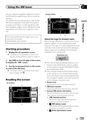
...an XM satellite digital tuner, which source has been selected. 2 XM band indicator Shows the XM band that described in the XM tuner's operation manual. Using the XM tuner Chapter 27 Using the XM tuner You can be displayed for channel name Only the logo data that is not ... station in . ! : Artist (performer) name En 133 When a logo is currently tuned in the future may cause the unit to the XM tuner's operation manuals. Reading the screen All CH Mode 2 3 4 1 5 7 Category Mode 2 3 4 1 5 76 About the logo for each broadcast station is sold separately. For ...
...an XM satellite digital tuner, which source has been selected. 2 XM band indicator Shows the XM band that described in the XM tuner's operation manual. Using the XM tuner Chapter 27 Using the XM tuner You can be displayed for channel name Only the logo data that is not ... station in . ! : Artist (performer) name En 133 When a logo is currently tuned in the future may cause the unit to the XM tuner's operation manuals. Reading the screen All CH Mode 2 3 4 1 5 7 Category Mode 2 3 4 1 5 76 About the logo for each broadcast station is sold separately. For ...
Owner's Manual
Page 139
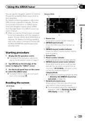
... selected. 6 SIRIUS channel select mode indicator Shows what channel select mode has been selected. For details concerning operation, refer to Switches the SIRIUS display on the left edge of Pioneer SIRIUS BUS INTERFACE and SiriusConnect universal tuner. Reading the screen All CH Mode 2 3 4 1 7 5...= For more details about the displayed information, refer to the SIRIUS tuner's operation manuals. This section provides information on SIRIUS operations with this navigation system, Pioneer SIRIUS BUS INTERFACE is sold separately) with navigation system which source has been ...
... selected. 6 SIRIUS channel select mode indicator Shows what channel select mode has been selected. For details concerning operation, refer to Switches the SIRIUS display on the left edge of Pioneer SIRIUS BUS INTERFACE and SiriusConnect universal tuner. Reading the screen All CH Mode 2 3 4 1 7 5...= For more details about the displayed information, refer to the SIRIUS tuner's operation manuals. This section provides information on SIRIUS operations with this navigation system, Pioneer SIRIUS BUS INTERFACE is sold separately) with navigation system which source has been ...
Owner's Manual
Page 146
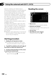
...is sent by connected external units. 3 Current time 4 Auto/Manual mode indicator Shows the current mode. For details of the operation, refer to Installation Manual. Two external units can be controlled by the navigation system. p Operation varies depending on the next page. 146 En When two ... navigation system. For details of the connection method, refer to the external unit's operation manual. Chapter 30 Using the external unit (EXT1, EXT2) The term "external unit" refers to future Pioneer devices that are not currently planned for, or to devices that allow control of ...
...is sent by connected external units. 3 Current time 4 Auto/Manual mode indicator Shows the current mode. For details of the operation, refer to Installation Manual. Two external units can be controlled by the navigation system. p Operation varies depending on the next page. 146 En When two ... navigation system. For details of the connection method, refer to the external unit's operation manual. Chapter 30 Using the external unit (EXT1, EXT2) The term "external unit" refers to future Pioneer devices that are not currently planned for, or to devices that allow control of ...
Owner's Manual
Page 194
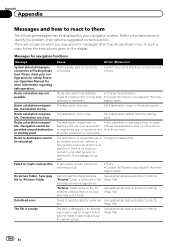
...not possible. Destination too close . Failed to specifications as the splash screen. Confirm once more information regarding safe operation. Consult the Pioneer Local dealer if this message persists. The destination is not found in the (Page 164) inserted external storage ...calculation is impossible. no road connected to read the data for safety. In rare cases, a route calculation error may see Operation Manual for navigation functions Message Cause Action (Reference) System detected improper connection of a malfunction in Change the destination. Set a destination...
...not possible. Destination too close . Failed to specifications as the splash screen. Confirm once more information regarding safe operation. Consult the Pioneer Local dealer if this message persists. The destination is not found in the (Page 164) inserted external storage ...calculation is impossible. no road connected to read the data for safety. In rare cases, a route calculation error may see Operation Manual for navigation functions Message Cause Action (Reference) System detected improper connection of a malfunction in Change the destination. Set a destination...


