Installation Manual
Page 2
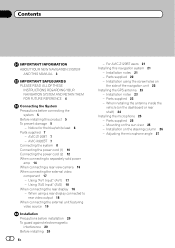
...the GPS antenna 23 - When using the screw holes on the steering column 26 - Parts supplied 23 - Adjusting the microphone angle 27 For AVIC-Z120BT users 21 Installing this product 5 To prevent damage 5 - Notice for the blue/white lead 6 Parts supplied 7 - Using "AV2 Input...- Installation using a rear display connected to separately sold power amp 14 When connecting a rear view camera 16 When connecting the external video component 17 - AVIC-X920BT 7 Connecting the system 8 Connecting the power cord (1) 10 Connecting the power cord (2) 12 When connecting to rear video output 18...
...the GPS antenna 23 - When using the screw holes on the steering column 26 - Parts supplied 23 - Adjusting the microphone angle 27 For AVIC-Z120BT users 21 Installing this product 5 To prevent damage 5 - Notice for the blue/white lead 6 Parts supplied 7 - Using "AV2 Input...- Installation using a rear display connected to separately sold power amp 14 When connecting a rear view camera 16 When connecting the external video component 17 - AVIC-X920BT 7 Connecting the system 8 Connecting the power cord (1) 10 Connecting the power cord (2) 12 When connecting to rear video output 18...
Installation Manual
Page 5
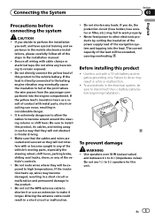
...result in the mobile electronics installations, please carefully follow all wiring with or become wound around the steering column or shift lever. Never feed power to do , the protection circuit (fuse holder, fuse resistor or filter, etc.) may result in considerable danger. ! Use this unit...metal parts, short-circuiting can occur, resulting in a fire or malfunction. ! Failure to other electronic products by cutting the insulation of the power supply lead of the lead will be exposed to 3 W speakers for this product to the product. ! The current capacity of the ...
...result in the mobile electronics installations, please carefully follow all wiring with or become wound around the steering column or shift lever. Never feed power to do , the protection circuit (fuse holder, fuse resistor or filter, etc.) may result in considerable danger. ! Use this unit...metal parts, short-circuiting can occur, resulting in a fire or malfunction. ! Failure to other electronic products by cutting the insulation of the power supply lead of the lead will be exposed to 3 W speakers for this product to the product. ! The current capacity of the ...
Installation Manual
Page 6
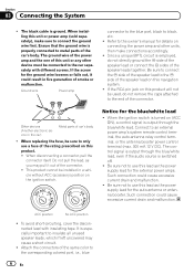
... speaker leads together. When replacing the fuse, be connected to the car separately with insulating tape. F ACC O F O Notice for the external power amps. Connect to black, etc. ! Be sure not to only use this product. ! If the screw for the auto-antenna or antenna booster...screws. Attach the connectors of the car's body. Section 03 Connecting the System ! If the RCA pin jack on this unit or power amp (sold separately), make connections accordingly. ! When the ignition switch is output through the blue/white lead. Such connection could cause ...
... speaker leads together. When replacing the fuse, be connected to the car separately with insulating tape. F ACC O F O Notice for the external power amps. Connect to black, etc. ! Be sure not to only use this product. ! If the screw for the auto-antenna or antenna booster...screws. Attach the connectors of the car's body. Section 03 Connecting the System ! If the RCA pin jack on this unit or power amp (sold separately), make connections accordingly. ! When the ignition switch is output through the blue/white lead. Such connection could cause ...
Installation Manual
Page 7
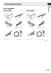
Connecting the System Section 03 Parts supplied AVIC-Z120BT AVIC-X920BT English The navigation unit Power cord The navigation unit Power cord GPS antenna USB and mini-jack connector GPS antenna USB and mini-jack connector RCA connector Microphone RCA connector Microphone En 7
Connecting the System Section 03 Parts supplied AVIC-Z120BT AVIC-X920BT English The navigation unit Power cord The navigation unit Power cord GPS antenna USB and mini-jack connector GPS antenna USB and mini-jack connector RCA connector Microphone RCA connector Microphone En 7
Installation Manual
Page 10
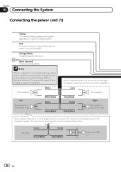
...Green Green/Black Violet Violet/Black Subwoofer (4 Ω) 2 10 En Section 03 Connecting the System Connecting the power cord (1) Yellow To terminal always supplied with green and green/black leads. Note When a subwoofer is monaural. Front speaker ... Subwoofer (4 Ω) White White/Black Green Green/Black With a 2 speaker system, do not connect anything with power regardless of a rear speaker, change the rear output setting in the Initial Setting. (Refer to speakers. Orange/White To lighting switch terminal...
...Green Green/Black Violet Violet/Black Subwoofer (4 Ω) 2 10 En Section 03 Connecting the System Connecting the power cord (1) Yellow To terminal always supplied with green and green/black leads. Note When a subwoofer is monaural. Front speaker ... Subwoofer (4 Ω) White White/Black Green Green/Black With a 2 speaker system, do not connect anything with power regardless of a rear speaker, change the rear output setting in the Initial Setting. (Refer to speakers. Orange/White To lighting switch terminal...
Installation Manual
Page 11
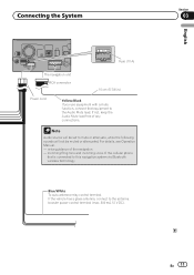
Connecting the System Fuse (10 A) The navigation unit RCA connector 15 cm (5-7/8 in.) Power cord Yellow/Black If you use equipment with a mute function, connect that is connected to this navigation system via Bluetooth wireless technology Blue/White To ... Operation Manual. - voice guidance of the cellular phone that equipment to the Audio Mute lead. Note Audio source will be set to the antenna booster power control terminal (max. 300 mA 12 V DC). incoming Ring tone and incoming voice of the navigation - If the vehicle has a glass antenna, connect to mute...
Connecting the System Fuse (10 A) The navigation unit RCA connector 15 cm (5-7/8 in.) Power cord Yellow/Black If you use equipment with a mute function, connect that is connected to this navigation system via Bluetooth wireless technology Blue/White To ... Operation Manual. - voice guidance of the cellular phone that equipment to the Audio Mute lead. Note Audio source will be set to the antenna booster power control terminal (max. 300 mA 12 V DC). incoming Ring tone and incoming voice of the navigation - If the vehicle has a glass antenna, connect to mute...
Installation Manual
Page 12
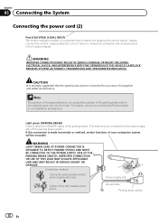
... OR USE OF THIS LEAD MAY VIOLATE APPLICABLE LAW AND MAY RESULT IN SERIOUS INJURY OR DAMAGE. Connection method Clamp the parking brake switch power supply side lead. For details, consult your navigation system will increase errors in the location display. Light green (PARKING BRAKE) Used to ...make this connection is made incorrectly or omitted, certain functions of your authorized Pioneer dealer or an installation professional. Failure to detect the ON/OFF status of the parking brake switch vary depending on the vehicle model.
... OR USE OF THIS LEAD MAY VIOLATE APPLICABLE LAW AND MAY RESULT IN SERIOUS INJURY OR DAMAGE. Connection method Clamp the parking brake switch power supply side lead. For details, consult your navigation system will increase errors in the location display. Light green (PARKING BRAKE) Used to ...make this connection is made incorrectly or omitted, certain functions of your authorized Pioneer dealer or an installation professional. Failure to detect the ON/OFF status of the parking brake switch vary depending on the vehicle model.
Installation Manual
Page 13
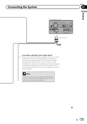
Connecting the System The navigation unit English Section 03 Power cord Violet/White (REVERSE GEAR SIGNAL INPUT) This is connected so that the navigation system can detect whether the vehicle is put in reverse. Connect ...
Connecting the System The navigation unit English Section 03 Power cord Violet/White (REVERSE GEAR SIGNAL INPUT) This is connected so that the navigation system can detect whether the vehicle is put in reverse. Connect ...
Installation Manual
Page 14
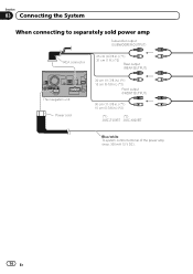
Section 03 Connecting the System When connecting to separately sold power amp Subwoofer output (SUBWOOFER OUTPUT) RCA connector 25 cm (9-7/8 in.) (*1) 31 cm (1 ft.) (*2) Rear output (REAR OUTPUT) The navigation unit Power cord 30 cm (11-7/8 in.) (*1) 15 cm (5-7/8 in.) (*2) Front output (FRONT OUTPUT) 30 cm (11-7/8 in.) (*1) 15 cm (5-7/8 in.) (*2) (*1) (*2) AVIC-Z120BT AVIC-X920BT Blue/white To system control terminal of the power amp (max. 300 mA 12 V DC). 14 En
Section 03 Connecting the System When connecting to separately sold power amp Subwoofer output (SUBWOOFER OUTPUT) RCA connector 25 cm (9-7/8 in.) (*1) 31 cm (1 ft.) (*2) Rear output (REAR OUTPUT) The navigation unit Power cord 30 cm (11-7/8 in.) (*1) 15 cm (5-7/8 in.) (*2) Front output (FRONT OUTPUT) 30 cm (11-7/8 in.) (*1) 15 cm (5-7/8 in.) (*2) (*1) (*2) AVIC-Z120BT AVIC-X920BT Blue/white To system control terminal of the power amp (max. 300 mA 12 V DC). 14 En
Installation Manual
Page 15
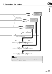
Connecting the System Section 03 English RCA cables (sold separately) Power amp (sold separately) Power amp (sold separately) Power amp (sold separately) System remote control Left Front speaker Rear speaker Right Front speaker Rear speaker Subwoofer Subwoofer Note You can change the RCA output of the subwoofer depending on your subwoofer system. (Refer to Operation Manual.) En 15
Connecting the System Section 03 English RCA cables (sold separately) Power amp (sold separately) Power amp (sold separately) Power amp (sold separately) System remote control Left Front speaker Rear speaker Right Front speaker Rear speaker Subwoofer Subwoofer Note You can change the RCA output of the subwoofer depending on your subwoofer system. (Refer to Operation Manual.) En 15
Installation Manual
Page 16
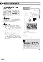
... rear view camera. It is necessary to Operation Manual.) ! ND-BC4) (sold separately) To video output RCA cable (*1) AVIC-Z120BT (*2) AVIC-X920BT Brown (REAR VIEW CAMERA IN) 20 cm (7-7/8 in.) (*1) 23 cm (9 in.) (*2) RCA connector Power cord The navigation unit Violet/white (REVERSE GEAR SIGNAL INPUT) For more distant than in "Back Camera Settings...
... rear view camera. It is necessary to Operation Manual.) ! ND-BC4) (sold separately) To video output RCA cable (*1) AVIC-Z120BT (*2) AVIC-X920BT Brown (REAR VIEW CAMERA IN) 20 cm (7-7/8 in.) (*1) 23 cm (9 in.) (*2) RCA connector Power cord The navigation unit Violet/white (REVERSE GEAR SIGNAL INPUT) For more distant than in "Back Camera Settings...
Installation Manual
Page 20
... vehicle's owner's manual for errors in the dash, door, or pillar from other damage to damage fuel lines, brake lines, electronic components, communication wires or power cables. ! Consult with the driver's opera- It could injure the driver or passengers if the vehicle stops suddenly. - Never install the navigation system in front...
... vehicle's owner's manual for errors in the dash, door, or pillar from other damage to damage fuel lines, brake lines, electronic components, communication wires or power cables. ! Consult with the driver's opera- It could injure the driver or passengers if the vehicle stops suddenly. - Never install the navigation system in front...
Installation Manual
Page 23
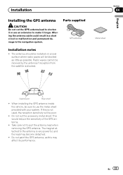
... poor. ! The antenna should be installed on a level surface where radio waves will be received by the antenna if reception from the satellite is very powerful, and the lead may affect its performance.
... poor. ! The antenna should be installed on a level surface where radio waves will be received by the antenna if reception from the satellite is very powerful, and the lead may affect its performance.
Owner's Manual
Page 173
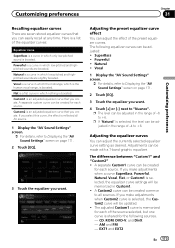
Powerful is shared for each of the source selected, but one curve is a curve in which is the human vocal range, is boosted. Adjusting the preset ... Displaying the "AV Sound Settings" screen on page 171. 2 Touch [EQ]. 3 Touch the equalizer you create. Natural is boosted. Powerful ! The difference between "Custom1" and "Custom2" ! If you make adjustments when a curve SuperBass, Powerful, Natural, Vocal, Flat, or Custom1 is an adjusted equalizer curve that you want . 4 Touch [+] or [-] next to +6. Flat...
Powerful is shared for each of the source selected, but one curve is a curve in which is the human vocal range, is boosted. Adjusting the preset ... Displaying the "AV Sound Settings" screen on page 171. 2 Touch [EQ]. 3 Touch the equalizer you create. Natural is boosted. Powerful ! The difference between "Custom1" and "Custom2" ! If you make adjustments when a curve SuperBass, Powerful, Natural, Vocal, Flat, or Custom1 is an adjusted equalizer curve that you want . 4 Touch [+] or [-] next to +6. Flat...
Owner's Manual
Page 189
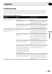
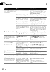
... The most common problems are correct. The Leads and connectors are causing the built-in microprocessor to your dealer or the nearest authorized Pioneer service facility. Noise and other factors are incor- racy. Check the GPS signal reception and the position of signals from the GPS ...right to the navigation system back on . If a solution to your vehicle The GPS antenna is in a safe place, and turn the power to distort positioning data for the fuse blowing, then replace the fuse. You cannot position your problem cannot be lost temporarily. positioning error. The...
... The most common problems are correct. The Leads and connectors are causing the built-in microprocessor to your dealer or the nearest authorized Pioneer service facility. Noise and other factors are incor- racy. Check the GPS signal reception and the position of signals from the GPS ...right to the navigation system back on . If a solution to your vehicle The GPS antenna is in a safe place, and turn the power to distort positioning data for the fuse blowing, then replace the fuse. You cannot position your problem cannot be lost temporarily. positioning error. The...
Owner's Manual
Page 190
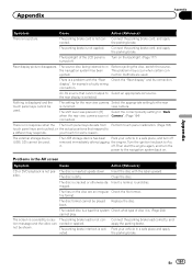
... navigation system may block positioning error. For details, refer to Installation Manual.) Indication of the position of the phone call is misaligned after a U-turn the power to automatically between daytime "Day". Check whether or not the reverse gear signal hicle is output echo: from the speakers and then picked -Lower the...
... navigation system may block positioning error. For details, refer to Installation Manual.) Indication of the position of the phone call is misaligned after a U-turn the power to automatically between daytime "Day". Check whether or not the reverse gear signal hicle is output echo: from the speakers and then picked -Lower the...
Owner's Manual
Page 191
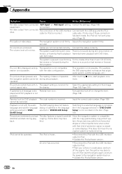
... setting for example a faulty wiring connection. view camera. off removed immediately after plugging the engine. There is selected. Problems in a safe place, and turn the power to Select an appropriate AV source. The source disc being listened to Acc it is no picture. Turn the ignition key back to in Before...
... setting for example a faulty wiring connection. view camera. off removed immediately after plugging the engine. There is selected. Problems in a safe place, and turn the power to Select an appropriate AV source. The source disc being listened to Acc it is no picture. Turn the ignition key back to in Before...
Owner's Manual
Page 192
.... back. An error has occurred. ! Connect the cables correctly. Switching to the navigation system back on . Park your vehicle in a safe place, and turn the power to a selected language is not possible if the language selected in "DVD/ DivX® Setup". Then start playback once more. The navigation system is not...
.... back. An error has occurred. ! Connect the cables correctly. Switching to the navigation system back on . Park your vehicle in a safe place, and turn the power to a selected language is not possible if the language selected in "DVD/ DivX® Setup". Then start playback once more. The navigation system is not...
Owner's Manual
Page 193
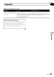
... screen becomes frozen... Retry after re-entering the range for dialing are inactive. Appendix En 193 Park your vehicle in a safe place, and turn the power to Acc off the engine. Your phone is not possible because the touch panel keys for service. The connection between the cellular Perform the connection...
... screen becomes frozen... Retry after re-entering the range for dialing are inactive. Appendix En 193 Park your vehicle in a safe place, and turn the power to Acc off the engine. Your phone is not possible because the touch panel keys for service. The connection between the cellular Perform the connection...
Owner's Manual
Page 214
... screen at temperatures higher or lower than 10 000 hours. Do not push the LCD screen with anything besides your dealer or the nearest authorized Pioneer Service Station. Small black dots or white dots (bright dots) may decrease if used inside the display to form inside the navigation unit, resulting ... product lifetime, the screen will become dimmer and the image will be visible. The LCD screen is not blowing on it , first turn the system power off, then wipe with an increase in possible damage. ! The LCD screen will no longer be difficult to see if it . If the LED backlight...
... screen at temperatures higher or lower than 10 000 hours. Do not push the LCD screen with anything besides your dealer or the nearest authorized Pioneer Service Station. Small black dots or white dots (bright dots) may decrease if used inside the display to form inside the navigation unit, resulting ... product lifetime, the screen will become dimmer and the image will be visible. The LCD screen is not blowing on it , first turn the system power off, then wipe with an increase in possible damage. ! The LCD screen will no longer be difficult to see if it . If the LED backlight...


