
Service Manual
Page 10
5021-0XX Preventive maintenance 6-1 Parts catalog 7-1 How to use this parts catalog 7-1 Index I-1 Part number index I-5 x Service Manual
5021-0XX Preventive maintenance 6-1 Parts catalog 7-1 How to use this parts catalog 7-1 Index I-1 Part number index I-5 x Service Manual

Service Manual
Page 26
...caution if the product must receive power in order to isolate failing field replaceable units (FRUs). 3. xxvi Service Manual Diagnostic aids contains tests and checks used to locate or repeat symptoms of the printer and the maintenance approach ...note provides additional information. Repair information provides instructions for individual FRUs. Parts catalog contains illustrations and part numbers for making printer adjustments and removing and installing FRUs. 5. 5021-0XX Preface This manual contains maintenance procedures for service personnel. Special tools and test equipment ...
...caution if the product must receive power in order to isolate failing field replaceable units (FRUs). 3. xxvi Service Manual Diagnostic aids contains tests and checks used to locate or repeat symptoms of the printer and the maintenance approach ...note provides additional information. Repair information provides instructions for individual FRUs. Parts catalog contains illustrations and part numbers for making printer adjustments and removing and installing FRUs. 5. 5021-0XX Preface This manual contains maintenance procedures for service personnel. Special tools and test equipment ...

Service Manual
Page 27
... tools and equipment: • Analog volt ohmmeter (a digital volt ohmmeter may find that the removals in this manual leads you complete the repair, perform tests as a shared network or desktop printer. Maintenance approach The diagnostic information...ring pliers When you identify parts. 1. The printer can be used as needed to the correct field replaceable unit (FRU) or part. See "Diagnostic information" on page 2-1, for presentations, business graphics, line art, and text. General information 1-1 General information 5021-0XX This Lexmark™ C510 color laser printer is ...
... tools and equipment: • Analog volt ohmmeter (a digital volt ohmmeter may find that the removals in this manual leads you complete the repair, perform tests as a shared network or desktop printer. Maintenance approach The diagnostic information...ring pliers When you identify parts. 1. The printer can be used as needed to the correct field replaceable unit (FRU) or part. See "Diagnostic information" on page 2-1, for presentations, business graphics, line art, and text. General information 1-1 General information 5021-0XX This Lexmark™ C510 color laser printer is ...

Service Manual
Page 48
5021-0XX Control system The control system consists of four control parts and runs the printer by processing the interface signals transmitted from the computer and the other printer systems such as the print, transfer, optical, and transport system: sequence control, laser control, fusing temperature control, and interface control. 1-22 Service Manual
5021-0XX Control system The control system consists of four control parts and runs the printer by processing the interface signals transmitted from the computer and the other printer systems such as the print, transfer, optical, and transport system: sequence control, laser control, fusing temperature control, and interface control. 1-22 Service Manual

Service Manual
Page 52
5021-0XX Structure of OPC belt (photo developer cartridge) The OPC belt consists of a surface layer having an optical photoconductor (OPC) of organic material, the inner layer consists of the print system. 1-26 Service Manual The OPC belt is a main part of an insulator material (PET), and the aluminum deposit layer in between.
5021-0XX Structure of OPC belt (photo developer cartridge) The OPC belt consists of a surface layer having an optical photoconductor (OPC) of organic material, the inner layer consists of the print system. 1-26 Service Manual The OPC belt is a main part of an insulator material (PET), and the aluminum deposit layer in between.

Service Manual
Page 66
... circuit 6 BTD mirror: beam timing detector mirror to guide the laser beam to PD 7 Scanner motor: rotates the polygon mirror 1-40 Service Manual 5021-0XX Details of following parts: No. The Optical printhead unit consists of the optical system In the optical system process, the printer utilizes a semiconductor laser diode as a light...
... circuit 6 BTD mirror: beam timing detector mirror to guide the laser beam to PD 7 Scanner motor: rotates the polygon mirror 1-40 Service Manual 5021-0XX Details of following parts: No. The Optical printhead unit consists of the optical system In the optical system process, the printer utilizes a semiconductor laser diode as a light...

Service Manual
Page 68
... roller synchronizes with the transfer belt. 1-42 Service Manual Feeds paper one , preventing multi-feed. During the fusing process, the fuser rollers transport the fused paper to the exit roller and the exit roller pushes the final paper out of the following parts: No. The paper transportation system consists of the ...pick-up roller 3 Registration roller Function Accommodates paper to be automatically fed through the printer. The registration roller transports the paper to the fuser rollers. Part 1 Paper tray 2 Pick-up roller and transported to the registration roller.
... roller synchronizes with the transfer belt. 1-42 Service Manual Feeds paper one , preventing multi-feed. During the fusing process, the fuser rollers transport the fused paper to the exit roller and the exit roller pushes the final paper out of the following parts: No. The paper transportation system consists of the ...pick-up roller 3 Registration roller Function Accommodates paper to be automatically fed through the printer. The registration roller transports the paper to the fuser rollers. Part 1 Paper tray 2 Pick-up roller and transported to the registration roller.
Service Manual
Page 70
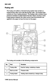
...utilizes a thermal fusing system that contains a heated fusing roller and a belt-like backup roller. The backup roller contains three pressure members located behind the belt. Part 1 Fusing roller 2 Back-up roller 3 Fusing heater Function Used for fusing, containing a heater. Pressure roller. Paper carrying a toner image passes between the... pressure are applied to the paper to fuse the toner to the paper. Heating device heated by a halogen lamp. 1-44 Service Manual The fusing unit consists of the following components: No. The heated roller contains an inner heating element.
...utilizes a thermal fusing system that contains a heated fusing roller and a belt-like backup roller. The backup roller contains three pressure members located behind the belt. Part 1 Fusing roller 2 Back-up roller 3 Fusing heater Function Used for fusing, containing a heater. Pressure roller. Paper carrying a toner image passes between the... pressure are applied to the paper to fuse the toner to the paper. Heating device heated by a halogen lamp. 1-44 Service Manual The fusing unit consists of the following components: No. The heated roller contains an inner heating element.

Service Manual
Page 74
... of printer. 2 Temperature control Controls temperature of fuser unit. 3 Consumables' life Controls toner empty status for each toner control cartridge and life of periodic replacement parts. 4 Operator panel Controls operator panel indication and control operator signals. 5 Error processing Senses errors occurring as well as stop control procedures. 6 Interface control Controls receipt... from external controller. 7 Laser control Controls laser scanning and laser power. Note: A micro CPU mounted on the engine board controls the print processes. 1-48 Service Manual
... of printer. 2 Temperature control Controls temperature of fuser unit. 3 Consumables' life Controls toner empty status for each toner control cartridge and life of periodic replacement parts. 4 Operator panel Controls operator panel indication and control operator signals. 5 Error processing Senses errors occurring as well as stop control procedures. 6 Interface control Controls receipt... from external controller. 7 Laser control Controls laser scanning and laser power. Note: A micro CPU mounted on the engine board controls the print processes. 1-48 Service Manual

Service Manual
Page 88
... exhausted state requiring that you answer another replacement message, and photodeveloper cartridge is a customer ordered part. Note: This is either in warning state, and message appears again each time top cover is opened . 2-10 Service Manual This message appears when the top door is closed or when you replace it. Press Stop...
... exhausted state requiring that you answer another replacement message, and photodeveloper cartridge is a customer ordered part. Note: This is either in warning state, and message appears again each time top cover is opened . 2-10 Service Manual This message appears when the top door is closed or when you replace it. Press Stop...

Service Manual
Page 98
...board connector FUCN and fuser. Otherwise, replace engine controller board. Go to "Engine controller board removal" on page 4-55. 2-20 Service Manual If cable is completely used. If cable is bad, replace cable. Otherwise, replace engine controller board. Go to "Engine controller board removal..." on page 4-55. 87 Fuser Life Warning Fuser is a customer ordered part. If problem persists, check cable for continuity that connects engine controller board connector FUCN and fuser. If problem persists, check cable for ...
...board connector FUCN and fuser. Otherwise, replace engine controller board. Go to "Engine controller board removal" on page 4-55. 2-20 Service Manual If cable is completely used. If cable is bad, replace cable. Otherwise, replace engine controller board. Go to "Engine controller board removal..." on page 4-55. 87 Fuser Life Warning Fuser is a customer ordered part. If problem persists, check cable for continuity that connects engine controller board connector FUCN and fuser. If problem persists, check cable for ...

Service Manual
Page 150
..." on page 4-11. Go to step 5. Note: Photodeveloper cartridge is a customer ordered part. 4 Check cable for shorted pins. Replace cable. 2-72 Service Manual damaged. high voltage contacts in printer. Is cable okay? See "Photodeveloper cartridge removal" on... cartridge is a customer ordered part. 2 Check charging unit Go to step 3. 3 Replace Problem solved....
..." on page 4-11. Go to step 5. Note: Photodeveloper cartridge is a customer ordered part. 4 Check cable for shorted pins. Replace cable. 2-72 Service Manual damaged. high voltage contacts in printer. Is cable okay? See "Photodeveloper cartridge removal" on... cartridge is a customer ordered part. 2 Check charging unit Go to step 3. 3 Replace Problem solved....

Service Manual
Page 178
Ensure fuser assembly guides and gears are not broken and are good. Ensure paper exit roller located in paper exit assembly is not damaged or dirty. Ensure paper exit gears and bearings are free of paper. Clean or replace parts if necessary. 2-100 Service Manual Check rear cover assembly for damage. 5021-0XX Problem area 7 Fuser assembly 8 • Paper exit assembly • Gears Action Ensure fuser assembly is not damaged. Note: Fuser assembly is a customer ordered supply. Ensure paper guides are not bent or dirty.
Ensure fuser assembly guides and gears are not broken and are good. Ensure paper exit roller located in paper exit assembly is not damaged or dirty. Ensure paper exit gears and bearings are free of paper. Clean or replace parts if necessary. 2-100 Service Manual Check rear cover assembly for damage. 5021-0XX Problem area 7 Fuser assembly 8 • Paper exit assembly • Gears Action Ensure fuser assembly is not damaged. Note: Fuser assembly is a customer ordered supply. Ensure paper guides are not bent or dirty.

Service Manual
Page 182
5021-0XX Black line service check A fine black line appears in printer image. Replace photodeveloper cartridge. See "Photodeveloper cartridge removal" on ) have adhered to perimeter parts of OPC belt and transfer belt. 2-104 Service Manual Clean perimeter of mounting area of OPC belt and transfer unit belt. Replace toner cartridge. OPC belt's surface is deformed. Problem area 1 Toner cartridge 2 Photodeveloper (OPC) cartridge 3 Debris Action Toner cartridge blade is damaged. Foreign particles (paper dust, and so on page 4-11.
5021-0XX Black line service check A fine black line appears in printer image. Replace photodeveloper cartridge. See "Photodeveloper cartridge removal" on ) have adhered to perimeter parts of OPC belt and transfer belt. 2-104 Service Manual Clean perimeter of mounting area of OPC belt and transfer unit belt. Replace toner cartridge. OPC belt's surface is deformed. Problem area 1 Toner cartridge 2 Photodeveloper (OPC) cartridge 3 Debris Action Toner cartridge blade is damaged. Foreign particles (paper dust, and so on page 4-11.

Service Manual
Page 196
... and clean waste toner auger and area around photodeveloper cartridge and transfer belt unit which consequently contact toner image on ) adhere to parts located around . Reinstall cleaning roller. 2-118 Service Manual Remove and clean photodeveloper cartridge, transfer belt unit, and adjacent areas. Problem area 1 Photodeveloper cartridge (OPC belt) and transfer belt 2 Transfer...
... and clean waste toner auger and area around photodeveloper cartridge and transfer belt unit which consequently contact toner image on ) adhere to parts located around . Reinstall cleaning roller. 2-118 Service Manual Remove and clean photodeveloper cartridge, transfer belt unit, and adjacent areas. Problem area 1 Photodeveloper cartridge (OPC belt) and transfer belt 2 Transfer...

Service Manual
Page 210
... Jam 201 - Paper Jam 202 - 5021-0XX Paper jam sequence Go to "Paper jam messages" on page 2-22 for signs of damage, contamination, or broken parts. • If media is jammed in or around fuser exit sensor area of fuser. • Check paper exit for more information. Indicates media is jamming...
... Jam 201 - Paper Jam 202 - 5021-0XX Paper jam sequence Go to "Paper jam messages" on page 2-22 for signs of damage, contamination, or broken parts. • If media is jammed in or around fuser exit sensor area of fuser. • Check paper exit for more information. Indicates media is jamming...
Service Manual
Page 234
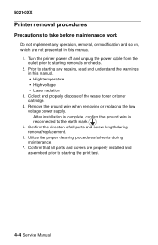
... any repairs, read and understand the warnings in this manual. • High temperature • High voltage • Laser radiation 3. Collect and properly dispose of all parts and covers are not presented in this manual. 1. Utilize the proper cleaning procedures/solvents during removal/replacement... or checks. 2. After installation is complete, confirm the ground wire is reconnected to starting the print test. 4-4 Service Manual Confirm that all parts and screw length during maintenance. 7. Turn the printer power off and unplug the power cable from the outlet prior to...
... any repairs, read and understand the warnings in this manual. • High temperature • High voltage • Laser radiation 3. Collect and properly dispose of all parts and covers are not presented in this manual. 1. Utilize the proper cleaning procedures/solvents during removal/replacement... or checks. 2. After installation is complete, confirm the ground wire is reconnected to starting the print test. 4-4 Service Manual Confirm that all parts and screw length during maintenance. 7. Turn the printer power off and unplug the power cable from the outlet prior to...

Service Manual
Page 272
Loosen two screws (A) of sensor base to allow free movement of reinstalling. The photo depicts proper removal and the first part of waste toner feeder. Remove main drive gear assembly. A 4-42 Service Manual This allows proper installation of the assembly. Waste toner feeder removal 1. Remove main drive gear assembly from printer. See "Main drive gear assembly removal" on page 4-41. 2. 5021-0XX 8. Note: When reinserting the main drive gear assembly, ensure that you start with the bottom right corner.
Loosen two screws (A) of sensor base to allow free movement of reinstalling. The photo depicts proper removal and the first part of waste toner feeder. Remove main drive gear assembly. A 4-42 Service Manual This allows proper installation of the assembly. Waste toner feeder removal 1. Remove main drive gear assembly from printer. See "Main drive gear assembly removal" on page 4-41. 2. 5021-0XX 8. Note: When reinserting the main drive gear assembly, ensure that you start with the bottom right corner.

Service Manual
Page 294
The sender portion of the toner sensor is comprised of two separate parts: the sender and receiver. Remove 2 screws (B); For cyan retract solenoid, remove LVPS with cage removal" on page 4-60. 2. 5021-0XX Toner sensor (receiver) removal Note: ... (sender) removal" on toner sensor (receiver). 3. For rest of retract solenoids, remove HVPS cage. Disconnect toner sensor cable from toner retract solenoid connector (A). 4-64 Service Manual
The sender portion of the toner sensor is comprised of two separate parts: the sender and receiver. Remove 2 screws (B); For cyan retract solenoid, remove LVPS with cage removal" on page 4-60. 2. 5021-0XX Toner sensor (receiver) removal Note: ... (sender) removal" on toner sensor (receiver). 3. For rest of retract solenoids, remove HVPS cage. Disconnect toner sensor cable from toner retract solenoid connector (A). 4-64 Service Manual

Service Manual
Page 306
... are located. Releases rear cover assembly. Opening the top cover assembly allows access to paper guide (A) and (B) assemblies. 5-2 Service Manual Turns the printer on and off. Printer front enclosure that supplies AC power to the printer. Connects the power cord that opens allowing...bottle replacement. Covers a portion of internal paper jams or maintenance work. Covers the right side of the duplex unit. 5021-0XX Part name Paper stopper Operator panel/cover Top cover assembly Rear cover assembly Release lever (rear cover assembly) Release lever (top cover assembly...
... are located. Releases rear cover assembly. Opening the top cover assembly allows access to paper guide (A) and (B) assemblies. 5-2 Service Manual Turns the printer on and off. Printer front enclosure that supplies AC power to the printer. Connects the power cord that opens allowing...bottle replacement. Covers a portion of internal paper jams or maintenance work. Covers the right side of the duplex unit. 5021-0XX Part name Paper stopper Operator panel/cover Top cover assembly Rear cover assembly Release lever (rear cover assembly) Release lever (top cover assembly...

