
Service Manual
Page 4
...diagram 1-49 Laser drive control circuit 1-50 Interface control 1-51 Diagnostic information 2-1 Start 2-1 Service error codes 2-2 Operator messages 2-9 Paper jam messages 2-22 Symptom tables 2-25 Printer symptom table 2-25 Print quality ...service check 2-37 906-Magenta toner retract solenoid service check 2-39 907-Cyan toner retract solenoid service check 2-41 908-Black toner retract solenoid service check 2-43 910-Developer motor service check 2-45 911-Main motor service check 2-48 912-Power supply fan service check 2-51 913-Fuser fan service check 2-52 iv Service Manual
...diagram 1-49 Laser drive control circuit 1-50 Interface control 1-51 Diagnostic information 2-1 Start 2-1 Service error codes 2-2 Operator messages 2-9 Paper jam messages 2-22 Symptom tables 2-25 Printer symptom table 2-25 Print quality ...service check 2-37 906-Magenta toner retract solenoid service check 2-39 907-Cyan toner retract solenoid service check 2-41 908-Black toner retract solenoid service check 2-43 910-Developer motor service check 2-45 911-Main motor service check 2-48 912-Power supply fan service check 2-51 913-Fuser fan service check 2-52 iv Service Manual

Service Manual
Page 6
... service check 2-108 Jitter service check 2-109 Missing image at edge service check 2-110 Mixed color image service check 2-111 Mottle service check 2-112 Residual image service check 2-113 Ribbing service check 2-114 Toner drop service check 2-116 Vertical line service check 2-118 Vertical staggering image service check 2-119 Vertical white band service check 2-120 White band service check 2-121 White line I service... test 3-11 Serial wrap test 3-11 Duplex tests 3-13 Duplex left margin 3-13 Device tests 3-14 Quick disk test 3-14 Disk test/clean 3-14 vi Service Manual
... service check 2-108 Jitter service check 2-109 Missing image at edge service check 2-110 Mixed color image service check 2-111 Mottle service check 2-112 Residual image service check 2-113 Ribbing service check 2-114 Toner drop service check 2-116 Vertical line service check 2-118 Vertical staggering image service check 2-119 Vertical white band service check 2-120 White band service check 2-121 White line I service... test 3-11 Serial wrap test 3-11 Duplex tests 3-13 Duplex left margin 3-13 Device tests 3-14 Quick disk test 3-14 Disk test/clean 3-14 vi Service Manual

Service Manual
Page 8
... 4-68 Marker sensor assembly removal 4-69 I/O board removal 4-70 Waste toner auger removal 4-72 Waste toner agitator removal 4-73 Power supply fan removal 4-74 viii Service Manual
... 4-68 Marker sensor assembly removal 4-69 I/O board removal 4-70 Waste toner auger removal 4-72 Waste toner agitator removal 4-73 Power supply fan removal 4-74 viii Service Manual

Service Manual
Page 10
5021-0XX Preventive maintenance 6-1 Parts catalog 7-1 How to use this parts catalog 7-1 Index I-1 Part number index I-5 x Service Manual
5021-0XX Preventive maintenance 6-1 Parts catalog 7-1 How to use this parts catalog 7-1 Index I-1 Part number index I-5 x Service Manual

Service Manual
Page 26
...tools and test equipment are working. Parts catalog contains illustrations and part numbers for service personnel. xxvi Service Manual 5021-0XX Preface This manual contains maintenance procedures for individual FRUs. Preventive maintenance contains the lubrication specifications and recommendations ...removing and installing FRUs. 5. Warning: A warning identifies something that might cause a servicer harm. Diagnostic information contains an error indicator table, symptom tables, and service checks used to identify the connector locations and test points on the printer. 6. ...
...tools and test equipment are working. Parts catalog contains illustrations and part numbers for service personnel. xxvi Service Manual 5021-0XX Preface This manual contains maintenance procedures for individual FRUs. Preventive maintenance contains the lubrication specifications and recommendations ...removing and installing FRUs. 5. Warning: A warning identifies something that might cause a servicer harm. Diagnostic information contains an error indicator table, symptom tables, and service checks used to identify the connector locations and test points on the printer. 6. ...

Service Manual
Page 28
The serial number is also listed in the menu settings page and can be printed from the utilities menu. 1-2 Service Manual 5021-0XX Serial number Look for the label on the rear cover of your printer for serial number information.
The serial number is also listed in the menu settings page and can be printed from the utilities menu. 1-2 Service Manual 5021-0XX Serial number Look for the label on the rear cover of your printer for serial number information.

Service Manual
Page 30
... Darkness menu. Auto (default): Applies different color correction to each object is specified. Off: No color correction is implemented. 1-4 Service Manual 5021-0XX Specifications Resolution 600 x 600 dpi 2400 image quality Model differences C510 C510n USB 2.0 X X Parallel X Ethernet X Memory (MB) 64 128 Options available 530-sheet drawer X X (tray 2) Duplex X X Hard disk X X C510dtn X X 128...
... Darkness menu. Auto (default): Applies different color correction to each object is specified. Off: No color correction is implemented. 1-4 Service Manual 5021-0XX Specifications Resolution 600 x 600 dpi 2400 image quality Model differences C510 C510n USB 2.0 X X Parallel X Ethernet X Memory (MB) 64 128 Options available 530-sheet drawer X X (tray 2) Duplex X X Hard disk X X C510dtn X X 128...
Service Manual
Page 32
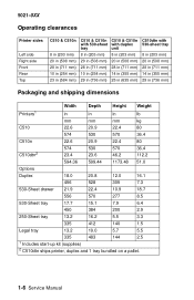
... tray 8 in (203 mm) 20 in (508 mm) 28 in (711 mm) 10 in (254 mm) 29 in (736 mm) C510 & C510n with duplex unit 8 in (203 mm) 20 in (508 mm) 28 in (711 mm) 14 in (355 mm) 25 ...(355 mm) 29 in (736 mm) Packaging and shipping dimensions Width Depth Height Weight Printers1 in in in lb mm mm mm kg C510 22.6 20.9 22.4 80 574 530 570 36.4 C510n 22.6 20.9 22.4 80 C510dtn2 574 530 570 36.4 23.4 23.6 ...Legal tray 13.2 19.0 5.7 5.5 335 483 144 2.5 1 Includes start-up kit (supplies) 2 C510dtn ships printer, duplex and 1 tray bundled on a pallet. 1-6 Service Manual
... tray 8 in (203 mm) 20 in (508 mm) 28 in (711 mm) 10 in (254 mm) 29 in (736 mm) C510 & C510n with duplex unit 8 in (203 mm) 20 in (508 mm) 28 in (711 mm) 14 in (355 mm) 25 ...(355 mm) 29 in (736 mm) Packaging and shipping dimensions Width Depth Height Weight Printers1 in in in lb mm mm mm kg C510 22.6 20.9 22.4 80 574 530 570 36.4 C510n 22.6 20.9 22.4 80 C510dtn2 574 530 570 36.4 23.4 23.6 ...Legal tray 13.2 19.0 5.7 5.5 335 483 144 2.5 1 Includes start-up kit (supplies) 2 C510dtn ships printer, duplex and 1 tray bundled on a pallet. 1-6 Service Manual

Service Manual
Page 34
..., the printable area is up to 4.0 mm (0.158 in.) of the top and bottom edges. 1-8 Service Manual Paper and media specifications Print area The C510 printable area is supported at a time, as well as only one month's usage) Machine life-120,000... pages/300,000 images Printer memory Memory configuration Standard DRAM Max DRAM C510 64MB C510n 128MB 320MB C510dtn 128MB Available memory options Optional 64MB and 128MB SDRAM DIMMs are available from the left ... 3.0 mm (0.118 in .) of the left and right edges, and 3.0 mm(0.118 in .) from Lexmark.
..., the printable area is up to 4.0 mm (0.158 in.) of the top and bottom edges. 1-8 Service Manual Paper and media specifications Print area The C510 printable area is supported at a time, as well as only one month's usage) Machine life-120,000... pages/300,000 images Printer memory Memory configuration Standard DRAM Max DRAM C510 64MB C510n 128MB 320MB C510dtn 128MB Available memory options Optional 64MB and 128MB SDRAM DIMMs are available from the left ... 3.0 mm (0.118 in .) of the left and right edges, and 3.0 mm(0.118 in .) from Lexmark.

Service Manual
Page 36
... should not be used. 2 Only occasional use of paper labels in an office environment is supported. 3 Only PN 12A5940 and 12A5941 should be used. 1-10 Service Manual tray Legal Sheet tray tray Duplex Printer menu Item Paper1,2 (grain long) Paper type Xerographic 60-74 or bond g/m2 60-74 g/m2 60-74...
... should not be used. 2 Only occasional use of paper labels in an office environment is supported. 3 Only PN 12A5940 and 12A5941 should be used. 1-10 Service Manual tray Legal Sheet tray tray Duplex Printer menu Item Paper1,2 (grain long) Paper type Xerographic 60-74 or bond g/m2 60-74 g/m2 60-74...

Service Manual
Page 38
... plastic-coated paper. • Recycled paper less than 75 g/m2 (20 lb) may be fed with short edge first, flap down Media guidelines With the Lexmark C510 print technology, paper designed for use with the printer. • Unsuitable papers include punched, embossed, water-marked, perforated media, any particular brand for laser printers... all sizes listed in the "Media sizes" table Capacity 250 sheets (20 lb paper) 50 Transparencies Orientation Collated Face down and to the right. 1-12 Service Manual
... plastic-coated paper. • Recycled paper less than 75 g/m2 (20 lb) may be fed with short edge first, flap down Media guidelines With the Lexmark C510 print technology, paper designed for use with the printer. • Unsuitable papers include punched, embossed, water-marked, perforated media, any particular brand for laser printers... all sizes listed in the "Media sizes" table Capacity 250 sheets (20 lb paper) 50 Transparencies Orientation Collated Face down and to the right. 1-12 Service Manual

Service Manual
Page 40
...8226; For serial attachment to the IBM AS/400 ASCII Workstation Controller, refer to the IBM AS/400 ASCII Workstation Reference and Example manual (SA41-9922) for attachment of the printer and must be ordered separately. • For serial attachment, optional RS-232C serial interface ... Optional network connections C510 C510n C510dtn Parallel & USB 2.0 Ethernet & USB Ethernet & USB 2.0 2.0 N/A 10/100 Base-TX 10/100 Base-TX Ethernet Ethernet RS-232 Serial/Parallel IEEE 1284-C Interface Card 10/100Base TX Ethernet, Token-Ring, 802.11b Wireless 1-14 Service Manual 5021-0XX •...
...8226; For serial attachment to the IBM AS/400 ASCII Workstation Controller, refer to the IBM AS/400 ASCII Workstation Reference and Example manual (SA41-9922) for attachment of the printer and must be ordered separately. • For serial attachment, optional RS-232C serial interface ... Optional network connections C510 C510n C510dtn Parallel & USB 2.0 Ethernet & USB Ethernet & USB 2.0 2.0 N/A 10/100 Base-TX 10/100 Base-TX Ethernet Ethernet RS-232 Serial/Parallel IEEE 1284-C Interface Card 10/100Base TX Ethernet, Token-Ring, 802.11b Wireless 1-14 Service Manual 5021-0XX •...

Service Manual
Page 42
...;F), Severe Low -10 to 0°C (14 to be continuous, but rather a total of such intermittent periods (48 hours at most for any one period). 1-16 Service Manual 5021-0XX Environment Environment Specifications Operating Air temperature - The period under severe shall not be deemed to 32°F). product operating 10 to 32.5°...
...;F), Severe Low -10 to 0°C (14 to be continuous, but rather a total of such intermittent periods (48 hours at most for any one period). 1-16 Service Manual 5021-0XX Environment Environment Specifications Operating Air temperature - The period under severe shall not be deemed to 32°F). product operating 10 to 32.5°...

Service Manual
Page 46
5021-0XX Printer paper path The following illustration shows the paper path and the associated paper jam messages for jams at specific points in the illustration has a duplex unit and secondary paper feed assembly installed: 1-20 Service Manual The printer depicted in the paper path.
5021-0XX Printer paper path The following illustration shows the paper path and the associated paper jam messages for jams at specific points in the illustration has a duplex unit and secondary paper feed assembly installed: 1-20 Service Manual The printer depicted in the paper path.

Service Manual
Page 48
5021-0XX Control system The control system consists of four control parts and runs the printer by processing the interface signals transmitted from the computer and the other printer systems such as the print, transfer, optical, and transport system: sequence control, laser control, fusing temperature control, and interface control. 1-22 Service Manual
5021-0XX Control system The control system consists of four control parts and runs the printer by processing the interface signals transmitted from the computer and the other printer systems such as the print, transfer, optical, and transport system: sequence control, laser control, fusing temperature control, and interface control. 1-22 Service Manual

Service Manual
Page 50
The toner is transferred to paper. 4. This printer has a toner cartridge for color combination. 3. The toner image formed on the transfer belt is fused to the transfer belt for each color - During the fusing process, the primary colors mix, yielding the desired color. 1-24 Service Manual 5021-0XX Basic process of color printing 1. yellow, magenta, cyan, and black. 2. The toner image is developed with primary colors and then transferred to the paper by the thermal fuser unit.
The toner is transferred to paper. 4. This printer has a toner cartridge for color combination. 3. The toner image formed on the transfer belt is fused to the transfer belt for each color - During the fusing process, the primary colors mix, yielding the desired color. 1-24 Service Manual 5021-0XX Basic process of color printing 1. yellow, magenta, cyan, and black. 2. The toner image is developed with primary colors and then transferred to the paper by the thermal fuser unit.

Service Manual
Page 52
5021-0XX Structure of OPC belt (photo developer cartridge) The OPC belt consists of a surface layer having an optical photoconductor (OPC) of organic material, the inner layer consists of the print system. 1-26 Service Manual The OPC belt is a main part of an insulator material (PET), and the aluminum deposit layer in between.
5021-0XX Structure of OPC belt (photo developer cartridge) The OPC belt consists of a surface layer having an optical photoconductor (OPC) of organic material, the inner layer consists of the print system. 1-26 Service Manual The OPC belt is a main part of an insulator material (PET), and the aluminum deposit layer in between.
Service Manual
Page 54
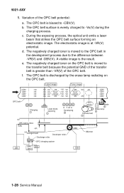
... -VR -V0Charge brush Discharge roller Developer roller OPC charging system -DBV TEST PRINT Transfer belt 4 Blade 6 Erase lamp 5 (M)toner -CBV -CHV DCV (-BRV) -DBV 1-28 Service Manual Variation of the OPC belt. The negatively charged toner is moved to the OPC belt in the development process due to the transfer belt because...
... -VR -V0Charge brush Discharge roller Developer roller OPC charging system -DBV TEST PRINT Transfer belt 4 Blade 6 Erase lamp 5 (M)toner -CBV -CHV DCV (-BRV) -DBV 1-28 Service Manual Variation of the OPC belt. The negatively charged toner is moved to the OPC belt in the development process due to the transfer belt because...

Service Manual
Page 56
Before charging, the OPC belt surface is -CBV(V). The charger unit evenly charges the OPC belt surface to -Vo(V) by generating a negative charge. 1-30 Service Manual 5021-0XX 3.
Before charging, the OPC belt surface is -CBV(V). The charger unit evenly charges the OPC belt surface to -Vo(V) by generating a negative charge. 1-30 Service Manual 5021-0XX 3.

Service Manual
Page 58
.... See "Printer theory of the OPC belt which begins the developing process. 2. The toner cartridges are four toner cartridges. Toner adheres to -DBV(V) potential. 1-32 Service Manual 5021-0XX Developing process In the developing process, an electrostatic latent image attracts printer toner and becomes visible on page 1-19 for toner cartridges location...
.... See "Printer theory of the OPC belt which begins the developing process. 2. The toner cartridges are four toner cartridges. Toner adheres to -DBV(V) potential. 1-32 Service Manual 5021-0XX Developing process In the developing process, an electrostatic latent image attracts printer toner and becomes visible on page 1-19 for toner cartridges location...


