
Service Manual
Page 4
... of the print system 1-29 Charging process 1-29 Exposing process 1-31 Developing process 1-32 First transfer (drum) process 1-34 Belt discharge (erase lamp) process 1-35 Belt cleaning process 1-36 Details of the transfer system 1-38 Second transfer (paper) process 1-38 Transfer belt cleaning process 1-39 Details of the optical system 1-40 Details of the paper transportation system...
... of the print system 1-29 Charging process 1-29 Exposing process 1-31 Developing process 1-32 First transfer (drum) process 1-34 Belt discharge (erase lamp) process 1-35 Belt cleaning process 1-36 Details of the transfer system 1-38 Second transfer (paper) process 1-38 Transfer belt cleaning process 1-39 Details of the optical system 1-40 Details of the paper transportation system...

Service Manual
Page 5
...63 986-Duplex connection error 2 service check 2-64 990-Transfer belt unit service check 2-65 991-Transfer roller clutch service check 2-67 992-Transfer belt cleaning roller clutch service check . . . . 2-68 993-Fuser clutch service check 2-69 994-OPC belt marker sensor service check 2-70 995-High voltage power supply...sensing service check 2-87 Printer no power service check 2-89 Toner feed service check 2-91 Toner low/empty service check 2-92 Transfer roller missing service check 2-93 Tray empty service check 2-95 Waste toner bottle service check 2-97 Waste toner feed service check...
...63 986-Duplex connection error 2 service check 2-64 990-Transfer belt unit service check 2-65 991-Transfer roller clutch service check 2-67 992-Transfer belt cleaning roller clutch service check . . . . 2-68 993-Fuser clutch service check 2-69 994-OPC belt marker sensor service check 2-70 995-High voltage power supply...sensing service check 2-87 Printer no power service check 2-89 Toner feed service check 2-91 Toner low/empty service check 2-92 Transfer roller missing service check 2-93 Tray empty service check 2-95 Waste toner bottle service check 2-97 Waste toner feed service check...

Service Manual
Page 7
... not to be touched 4-3 Printer removal procedures 4-4 Precautions to take before maintenance work 4-4 CRU/FRU and supplies removals 4-5 Cleaning roller cover removal 4-6 Transfer belt cleaning roller removal 4-6 Transfer belt unit removal 4-7 Transfer roller removal 4-8 Fuser assembly removal 4-9 Waste toner bottle removal 4-10 Photodeveloper cartridge removal 4-11 Duplex unit assembly removal 4-13 Secondary paper feed assembly...
... not to be touched 4-3 Printer removal procedures 4-4 Precautions to take before maintenance work 4-4 CRU/FRU and supplies removals 4-5 Cleaning roller cover removal 4-6 Transfer belt cleaning roller removal 4-6 Transfer belt unit removal 4-7 Transfer roller removal 4-8 Fuser assembly removal 4-9 Waste toner bottle removal 4-10 Photodeveloper cartridge removal 4-11 Duplex unit assembly removal 4-13 Secondary paper feed assembly...

Service Manual
Page 47
... control system. Mechanical and electrical structures This color laser printer consists of three functional parts that transfers the toner image formed on the transfer belt to paper: transfer belt unit, second transfer, and cleaning roller. Basic principles of color printing Color printing is made through the subtractive process...parts that picks up paper from the paper tray, separates the transported paper from the transfer belt, and exits it from the printer after fusing the toner image on the OPC belt using a laser light: optical unit and scanner motor (SCM). Optical system The ...
... control system. Mechanical and electrical structures This color laser printer consists of three functional parts that transfers the toner image formed on the transfer belt to paper: transfer belt unit, second transfer, and cleaning roller. Basic principles of color printing Color printing is made through the subtractive process...parts that picks up paper from the paper tray, separates the transported paper from the transfer belt, and exits it from the printer after fusing the toner image on the OPC belt using a laser light: optical unit and scanner motor (SCM). Optical system The ...

Service Manual
Page 50
The toner image formed on the transfer belt is fused to the paper by the thermal fuser unit. The toner is transferred to the transfer belt for each color - The toner image is developed with primary colors and then transferred to paper. 4. 5021-0XX Basic process of color printing 1. This printer has a toner cartridge for color combination. 3. During the fusing process, the primary colors mix, yielding the desired color. 1-24 Service Manual yellow, magenta, cyan, and black. 2.
The toner image formed on the transfer belt is fused to the paper by the thermal fuser unit. The toner is transferred to the transfer belt for each color - The toner image is developed with primary colors and then transferred to paper. 4. 5021-0XX Basic process of color printing 1. This printer has a toner cartridge for color combination. 3. During the fusing process, the primary colors mix, yielding the desired color. 1-24 Service Manual yellow, magenta, cyan, and black. 2.

Service Manual
Page 51
A color print is accomplished by actuating each process in the print system and the transfer system. General information 1-25 5021-0XX Print system and transfer system This illustration shows the basic structure of the print system having the OPC belt as a main function, and the transfer system including the transfer belt.
A color print is accomplished by actuating each process in the print system and the transfer system. General information 1-25 5021-0XX Print system and transfer system This illustration shows the basic structure of the print system having the OPC belt as a main function, and the transfer system including the transfer belt.
Service Manual
Page 54
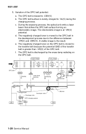
...The negatively charged toner is evenly charged to the difference between -VR(V) and -DBV(V). The electrostatic image is biased to the transfer belt because the potential GND of the transfer belt is the result. Latent image Toner image -CBV -CBV -CBV -CBV -V0 -V0 -V0 -V0 -V0 -V0... Developer roller OPC charging system -DBV TEST PRINT Transfer belt 4 Blade 6 Erase lamp 5 (M)toner -CBV -CHV DCV (-BRV) -DBV 1-28 Service Manual c. Variation of the OPC belt. d. e. The negatively charged toner on the OPC belt. The OPC belt is at -VR(V) potential. During the exposing ...
...The negatively charged toner is evenly charged to the difference between -VR(V) and -DBV(V). The electrostatic image is biased to the transfer belt because the potential GND of the transfer belt is the result. Latent image Toner image -CBV -CBV -CBV -CBV -V0 -V0 -V0 -V0 -V0 -V0... Developer roller OPC charging system -DBV TEST PRINT Transfer belt 4 Blade 6 Erase lamp 5 (M)toner -CBV -CHV DCV (-BRV) -DBV 1-28 Service Manual c. Variation of the OPC belt. d. e. The negatively charged toner on the OPC belt. The OPC belt is at -VR(V) potential. During the exposing ...

Service Manual
Page 60
... tube Film (transfer belt) 2. Toner on the OPC belt being transferred to the transfer belt. After the development process, the OPC belt rotates making contact and synchronizing with the transfer belt and the aluminum drum. The potential of a special rubber. The transfer belt is composed of the transfer belt and drum is nearly GND. 3. The OPC belt has been biased to the transfer belt and the...
... tube Film (transfer belt) 2. Toner on the OPC belt being transferred to the transfer belt. After the development process, the OPC belt rotates making contact and synchronizing with the transfer belt and the aluminum drum. The potential of a special rubber. The transfer belt is composed of the transfer belt and drum is nearly GND. 3. The OPC belt has been biased to the transfer belt and the...

Service Manual
Page 64
... causes the toner to release from the transfer belt, is transferred to the paper. 1-38 Service Manual The transfer roller contacts the transfer belt as paper passes between the transfer roller and the transfer belt. The transfer roller, normally separated from the transfer belt and adhere to paper. See "Printer theory of operation" on the transfer belt is positively biased by the power supply...
... causes the toner to release from the transfer belt, is transferred to the paper. 1-38 Service Manual The transfer roller contacts the transfer belt as paper passes between the transfer roller and the transfer belt. The transfer roller, normally separated from the transfer belt and adhere to paper. See "Printer theory of operation" on the transfer belt is positively biased by the power supply...

Service Manual
Page 65
... turn contacts the surface of the cleaning brush against the cleaning roller charges the brush. The cleaning brush does not contact the transfer belt during the imaging process. The negatively charged toner adheres to the waste toner container where it is charged by the waste toner feeder... to the positively charged (FCBV) brush, which cleans the transfer belt. See "Printer theory of operation" on the surface of the transfer belt is a semiconductor-type fur brush. Waste toner, adhering to the surface of the cleaning roller, is removed ...
... turn contacts the surface of the cleaning brush against the cleaning roller charges the brush. The cleaning brush does not contact the transfer belt during the imaging process. The negatively charged toner adheres to the waste toner container where it is charged by the waste toner feeder... to the positively charged (FCBV) brush, which cleans the transfer belt. See "Printer theory of operation" on the surface of the transfer belt is a semiconductor-type fur brush. Waste toner, adhering to the surface of the cleaning roller, is removed ...

Service Manual
Page 68
The paper transportation system consists of the rear cover assembly. During the transfer process, the transfer roller forwards the paper to the transfer roller. During the fusing process, the fuser rollers transport the fused paper to the exit roller and the ...parts: No. The registration roller transports the paper to the fuser rollers. The registration roller synchronizes with the transfer belt. 1-42 Service Manual Transports and synchronizes paper with the transfer belt. Part 1 Paper tray 2 Pick-up roller and transported to be automatically fed through the printer. Feeds ...
The paper transportation system consists of the rear cover assembly. During the transfer process, the transfer roller forwards the paper to the transfer roller. During the fusing process, the fuser rollers transport the fused paper to the exit roller and the ...parts: No. The registration roller transports the paper to the fuser rollers. The registration roller synchronizes with the transfer belt. 1-42 Service Manual Transports and synchronizes paper with the transfer belt. Part 1 Paper tray 2 Pick-up roller and transported to be automatically fed through the printer. Feeds ...

Service Manual
Page 69
Utilizes a heat roller to fuse the toner image to the fuser. Part Transfer roller 4 5 Fuser unit 6 Paper exit roller Function Works in conjunction with the transfer belt to transfer the image to paper and to transport the paper to the paper. Exits the fused paper from the printer. General information 1-43 5021-0XX No.
Utilizes a heat roller to fuse the toner image to the fuser. Part Transfer roller 4 5 Fuser unit 6 Paper exit roller Function Works in conjunction with the transfer belt to transfer the image to paper and to transport the paper to the paper. Exits the fused paper from the printer. General information 1-43 5021-0XX No.
Service Manual
Page 86
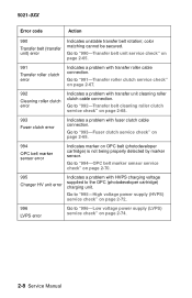
... "992-Transfer belt cleaning roller clutch service check" on page 2-65. 991 Transfer roller clutch error Indicates a problem with fuser clutch cable connection. Go to "990-Transfer belt unit service check" on page 2-68. 993 Fuser clutch error Indicates a problem with transfer roller cable connection. 5021-0XX Error code Action 990 Transfer belt (transfer unit) error Indicates unstable transfer belt rotation;
... "992-Transfer belt cleaning roller clutch service check" on page 2-65. 991 Transfer roller clutch error Indicates a problem with fuser clutch cable connection. Go to "990-Transfer belt unit service check" on page 2-68. 993 Fuser clutch error Indicates a problem with transfer roller cable connection. 5021-0XX Error code Action 990 Transfer belt (transfer unit) error Indicates unstable transfer belt rotation;

Service Manual
Page 103
...page 2-91. See "Operator messages" on page 2-9 and follow the action suggested. See "Toner feed service check" on page 2-48. See "990-Transfer belt unit service check" on page 2-84. See "Operator panel service check" on page 2-65. See "Operator panel service check" on page 2-84. ...Diagnostic information 2-25 Developer motor makes noise or continuously runs Main motor makes noise or continuously runs Transfer belt unit makes noise when rotated or does not rotate at all doors are closed Printer does not reset or change user settings Paper...
...page 2-91. See "Operator messages" on page 2-9 and follow the action suggested. See "Toner feed service check" on page 2-48. See "990-Transfer belt unit service check" on page 2-84. See "Operator panel service check" on page 2-65. See "Operator panel service check" on page 2-84. ...Diagnostic information 2-25 Developer motor makes noise or continuously runs Main motor makes noise or continuously runs Transfer belt unit makes noise when rotated or does not rotate at all doors are closed Printer does not reset or change user settings Paper...

Service Manual
Page 143
.... Go to step 2. If problem persists, go to rotate? Are belt markers "Transfer belt step 3. Replace transfer belt marker sensor. Diagnostic information 2-65 If markers stained? See "I /O board shield. Are cotton cloth. deformed or does transfer unit removal" belt seem hard to step 2. 2 Remove transfer belt unit Replace transfer Reinstall transfer and observe markers on lead of bracket assembly. and check...
.... Go to step 2. If problem persists, go to rotate? Are belt markers "Transfer belt step 3. Replace transfer belt marker sensor. Diagnostic information 2-65 If markers stained? See "I /O board shield. Are cotton cloth. deformed or does transfer unit removal" belt seem hard to step 2. 2 Remove transfer belt unit Replace transfer Reinstall transfer and observe markers on lead of bracket assembly. and check...

Service Manual
Page 146
...(cable) to connector that attaches to Check cable continuity from step 3. Check cable board removal" that pins are not shorted. Disconnect transfer belt cleaning roller clutch from problem DCN10 on I /O board shield. Is cable okay? 3 Remove engine controller Replace engine Replace cable. engine...on page 4-22. See "Engine controller board. See "Cleaning roller clutch removal" on I /O board shield. 5021-0XX 992-Transfer belt cleaning roller clutch service check Step Questions / actions Yes No 1 Turn printer off and remove Go to controller remove shield. If ...
...(cable) to connector that attaches to Check cable continuity from step 3. Check cable board removal" that pins are not shorted. Disconnect transfer belt cleaning roller clutch from problem DCN10 on I /O board shield. Is cable okay? 3 Remove engine controller Replace engine Replace cable. engine...on page 4-22. See "Engine controller board. See "Cleaning roller clutch removal" on I /O board shield. 5021-0XX 992-Transfer belt cleaning roller clutch service check Step Questions / actions Yes No 1 Turn printer off and remove Go to controller remove shield. If ...

Service Manual
Page 176
...? See auger damaged? and opening in bottom of toner feeder. agitator damaged? 5021-0XX Waste toner feed service check Step Questions / actions Yes No 1 Is transfer belt unit cleaning Go to step 4. clutch. for overflow. Is waste toner See "Waste feeder damaged?
...? See auger damaged? and opening in bottom of toner feeder. agitator damaged? 5021-0XX Waste toner feed service check Step Questions / actions Yes No 1 Is transfer belt unit cleaning Go to step 4. clutch. for overflow. Is waste toner See "Waste feeder damaged?

Service Manual
Page 177
...free from high humidity. 2 Paper tray 3 • Paper feed roller • Separator pad 4 • Registration roller • Transfer roller 5 Transfer belt unit Note: Disconnect secondary paper assembly and duplex unit, if installed, to help isolate a paper transport problem. Replace cleaning roller if necessary.... Check for wear or damage. Ensure no paper is free of foreign material. 6 Transfer belt unit cleaning roller Note: Do not touch transfer belt with your hands. Replace any damaged parts. Check paper feed roller and separator pad for paper caught ...
...free from high humidity. 2 Paper tray 3 • Paper feed roller • Separator pad 4 • Registration roller • Transfer roller 5 Transfer belt unit Note: Disconnect secondary paper assembly and duplex unit, if installed, to help isolate a paper transport problem. Replace cleaning roller if necessary.... Check for wear or damage. Ensure no paper is free of foreign material. 6 Transfer belt unit cleaning roller Note: Do not touch transfer belt with your hands. Replace any damaged parts. Check paper feed roller and separator pad for paper caught ...

Service Manual
Page 181
See "Photodeveloper cartridge removal" on page 4-11. Replace toner cartridge. Replace photodeveloper cartridge. Banding service check 5021-0XX A banding line appears in horizontal direction. Diagnostic information 2-103 Problem area 1 Photodeveloper (OPC) cartridge 2 Toner cartridge Action Transfer failure due to impact created during retract of the OPC belt passes over the cleaning blade. OPC belt and transfer belt fail to maintain regular and proper rotation due to uneven rotational speed caused by a shock which occurs when the seam of toner cartridge.
See "Photodeveloper cartridge removal" on page 4-11. Replace toner cartridge. Replace photodeveloper cartridge. Banding service check 5021-0XX A banding line appears in horizontal direction. Diagnostic information 2-103 Problem area 1 Photodeveloper (OPC) cartridge 2 Toner cartridge Action Transfer failure due to impact created during retract of the OPC belt passes over the cleaning blade. OPC belt and transfer belt fail to maintain regular and proper rotation due to uneven rotational speed caused by a shock which occurs when the seam of toner cartridge.

Service Manual
Page 182
Replace photodeveloper cartridge. Clean perimeter of mounting area of OPC belt and transfer unit belt. 5021-0XX Black line service check A fine black line appears in printer image. See "Photodeveloper cartridge removal" on ) have adhered to perimeter parts of OPC belt and transfer belt. 2-104 Service Manual Replace toner cartridge. Foreign particles (paper dust, and so on page 4-11. OPC belt's surface is deformed. Problem area 1 Toner cartridge 2 Photodeveloper (OPC) cartridge 3 Debris Action Toner cartridge blade is damaged.
Replace photodeveloper cartridge. Clean perimeter of mounting area of OPC belt and transfer unit belt. 5021-0XX Black line service check A fine black line appears in printer image. See "Photodeveloper cartridge removal" on ) have adhered to perimeter parts of OPC belt and transfer belt. 2-104 Service Manual Replace toner cartridge. Foreign particles (paper dust, and so on page 4-11. OPC belt's surface is deformed. Problem area 1 Toner cartridge 2 Photodeveloper (OPC) cartridge 3 Debris Action Toner cartridge blade is damaged.


