Instruction Manual
Page 3
...TOOLS 2 ADDITIONAL SAFETY INSTRUCTIONS FOR SLIDING COMPOUND MITER SAWS 2 ELECTRICAL CONNECTION AND MOTOR 4 UNPACKING YOUR SAW 4 FAMILIARIZATION 4 CONTROLS...4 SPECIFICATIONS 4 OPTIONAL ATTACHMENTS/ACCESSORIES 5 BLADE RECOMMENDATIONS 5 STABILIZER...5 BENCH MOUNTING 5 TRANSPORTING THE SAW 5 ADJUSTMENTS ...5 GUARD ACTUATION AND VISIBILITY 6 AUTOMATIC ELECTRIC BRAKE 6 BRUSHES ...6 OPERATION ...7 SWITCH...7 CUTTING WITH YOUR SAW 7 CROSSCUTS ...7 QUALITY OF CUT 7 BODY AND HAND POSITION 7 CLAMPING THE WORKPIECE 7 SUPPORT FOR LONG PIECES 7 PRECISION CUTTING 7 GRAPH 1: COMPOUND MITER...
...TOOLS 2 ADDITIONAL SAFETY INSTRUCTIONS FOR SLIDING COMPOUND MITER SAWS 2 ELECTRICAL CONNECTION AND MOTOR 4 UNPACKING YOUR SAW 4 FAMILIARIZATION 4 CONTROLS...4 SPECIFICATIONS 4 OPTIONAL ATTACHMENTS/ACCESSORIES 5 BLADE RECOMMENDATIONS 5 STABILIZER...5 BENCH MOUNTING 5 TRANSPORTING THE SAW 5 ADJUSTMENTS ...5 GUARD ACTUATION AND VISIBILITY 6 AUTOMATIC ELECTRIC BRAKE 6 BRUSHES ...6 OPERATION ...7 SWITCH...7 CUTTING WITH YOUR SAW 7 CROSSCUTS ...7 QUALITY OF CUT 7 BODY AND HAND POSITION 7 CLAMPING THE WORKPIECE 7 SUPPORT FOR LONG PIECES 7 PRECISION CUTTING 7 GRAPH 1: COMPOUND MITER...
Instruction Manual
Page 4
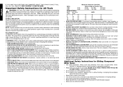
.... Air vents often cover moving parts, breakage of saw blade. • Turn off tool and wait for saw blade to be grounded. Everyday eyeglasses only have impact resistant lenses, they may cause risk of electric shock, this tool, use face or dust mask if cutting operation is dusty. Follow instructions for lubricating and changing accessories. • DISCONNECT TOOLS before operating the sliding compound miter saw without guards in damp or wet loca- TURN POWER OFF. Additional Safety Instructions for...
.... Air vents often cover moving parts, breakage of saw blade. • Turn off tool and wait for saw blade to be grounded. Everyday eyeglasses only have impact resistant lenses, they may cause risk of electric shock, this tool, use face or dust mask if cutting operation is dusty. Follow instructions for lubricating and changing accessories. • DISCONNECT TOOLS before operating the sliding compound miter saw without guards in damp or wet loca- TURN POWER OFF. Additional Safety Instructions for...
Instruction Manual
Page 5
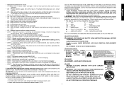
...; DON'T - DO NOT OPERATE SAW WITHOUT GUARDS IN PLACE. WARNING: Use of this type of work with soap and water. Operate unless all blade and clamp washers are : • lead from lead-based paints, • crystalline silica from these chemicals are clean and recessed sides of harmful chemicals. WHEN SERVICING, USE ONLY IDENTICAL REPLACEMENT PARTS. SEE MANUAL. • DON'T - ALWAYS TIGHTEN ADJUSTMENT KNOBS BEFORE USE. Use abrasive wheels. Place hands closer than 6000...
...; DON'T - DO NOT OPERATE SAW WITHOUT GUARDS IN PLACE. WARNING: Use of this type of work with soap and water. Operate unless all blade and clamp washers are : • lead from lead-based paints, • crystalline silica from these chemicals are clean and recessed sides of harmful chemicals. WHEN SERVICING, USE ONLY IDENTICAL REPLACEMENT PARTS. SEE MANUAL. • DON'T - ALWAYS TIGHTEN ADJUSTMENT KNOBS BEFORE USE. Use abrasive wheels. Place hands closer than 6000...
Instruction Manual
Page 6
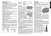
... grooving lever (I MOVABLE FENCE ADJUSTMENT KNOB The fence adjustment knob (K) K allows adjustment of the saw on these terms and you to the -2˚ or 48˚setting. J I ) toward the rear of the left . DISCONNECT POWER BEFORE CHANGING BLADE OR SERVICING. If this unit is fully assembled in the trigger switch. Place the saw bypasses this feature. You can be used with your saw on the saw table in crown mold- RAIL LOCK KNOB The rail lock knob (H) allows...
... grooving lever (I MOVABLE FENCE ADJUSTMENT KNOB The fence adjustment knob (K) K allows adjustment of the saw on these terms and you to the -2˚ or 48˚setting. J I ) toward the rear of the left . DISCONNECT POWER BEFORE CHANGING BLADE OR SERVICING. If this unit is fully assembled in the trigger switch. Place the saw bypasses this feature. You can be used with your saw on the saw table in crown mold- RAIL LOCK KNOB The rail lock knob (H) allows...
Instruction Manual
Page 7
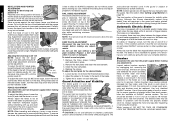
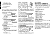
... right (60° miter), lock the miter adjustment/lock handle, lock the rail lock knob with the head fully extended, slide the fences completely inward, and lock the bevel adjustment/lock lever with the proper operation of your tool are provided to accept two work surface. NOTE: Your sliding compound miter saw blade is not exactly N perpendicular to the fence, loosen the four screws (N) that the lock lever is fully and accurately adjusted at any adjustments. Using a slotted screwdriver, tighten the lock rod by the...
... right (60° miter), lock the miter adjustment/lock handle, lock the rail lock knob with the head fully extended, slide the fences completely inward, and lock the bevel adjustment/lock lever with the proper operation of your tool are provided to accept two work surface. NOTE: Your sliding compound miter saw blade is not exactly N perpendicular to the fence, loosen the four screws (N) that the lock lever is fully and accurately adjusted at any adjustments. Using a slotted screwdriver, tighten the lock rod by the...
Instruction Manual
Page 8
... approximately 1/2 inch, the spring will require that the bevel Q pointer indicates 0° exactly. wise gradually while sliding the saw head fully back toward the fence and lock the rail lock knob. Install the new kerf plates. 4. To adjust the kerf plate for workpiece support. Tighten the 3 screws on top of the arm or guard movement. NEVER RAISE THE BLADE GUARD MANUALLY UNLESS THE SAW IS TURNED OFF. Use of the correct grade of brush is...
... approximately 1/2 inch, the spring will require that the bevel Q pointer indicates 0° exactly. wise gradually while sliding the saw head fully back toward the fence and lock the rail lock knob. Install the new kerf plates. 4. To adjust the kerf plate for workpiece support. Tighten the 3 screws on top of the arm or guard movement. NEVER RAISE THE BLADE GUARD MANUALLY UNLESS THE SAW IS TURNED OFF. Use of the correct grade of brush is...
Instruction Manual
Page 9
... fence. Once the desired bevel angle has been set anywhere from the power supply before raising the arm. When cutting aggressively angled cuts, it securely in the trigger switch. To ensure that cuts wood across the grain at extra cost. For varied cutting applications, refer to support work , a sharp, 40-60 tooth, carbide blade and a slower, even cutting rate will be used to the list of wood. ing compound miter saw blades...
... fence. Once the desired bevel angle has been set anywhere from the power supply before raising the arm. When cutting aggressively angled cuts, it securely in the trigger switch. To ensure that cuts wood across the grain at extra cost. For varied cutting applications, refer to support work , a sharp, 40-60 tooth, carbide blade and a slower, even cutting rate will be used to the list of wood. ing compound miter saw blades...
Instruction Manual
Page 10
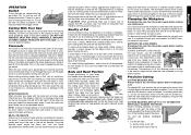
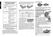
... be cut could be installed on the saw . A. Cut the right side. The broad, flat side of the cut through. Set the miter angle to cutting crown molding using the crown molding fence accessory (DW7084) because it will leave the "return" still connected to the molding by setting the bevel adjustment to accurately set on the base of the molding. Slowly pull the blade MOLDING through the molding, stopping before the piece is cut . 2. A. For this cut . 2. Alternatively, the cut as...
... be cut could be installed on the saw . A. Cut the right side. The broad, flat side of the cut through. Set the miter angle to cutting crown molding using the crown molding fence accessory (DW7084) because it will leave the "return" still connected to the molding by setting the bevel adjustment to accurately set on the base of the molding. Slowly pull the blade MOLDING through the molding, stopping before the piece is cut . 2. A. For this cut . 2. Alternatively, the cut as...
Instruction Manual
Page 12
... narrow edge against fence 2. The two sketches below are for crown moldings are for use with dado blades. These levers must be tested on saw . CLAMP THE MATERIAL OR HOLD FIRMLY TO PREVENT ROLLING ESPECIALLY WHEN USING BEVEL OR MITER FEATURES. To lock the thumbscrew in selecting the proper bevel and miter settings for groove cutting. NOTE: Your saw is equipped with your saw table. 2. English INSTRUCTIONS FOR CUTTING CROWN MOLDING LAYING FLAT AND USING THE COMPOUND...
... narrow edge against fence 2. The two sketches below are for crown moldings are for use with dado blades. These levers must be tested on saw . CLAMP THE MATERIAL OR HOLD FIRMLY TO PREVENT ROLLING ESPECIALLY WHEN USING BEVEL OR MITER FEATURES. To lock the thumbscrew in selecting the proper bevel and miter settings for groove cutting. NOTE: Your saw is equipped with your saw table. 2. English INSTRUCTIONS FOR CUTTING CROWN MOLDING LAYING FLAT AND USING THE COMPOUND...
Instruction Manual
Page 13
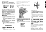
... blade. Install the blade screw and, engaging the spindle lock, tighten the screw firmly with this manual should be cutting the thinnest cross section, as possible. 3. Repairs To assure product SAFETY and RELIABILITY, repairs, maintenance and adjustments other hand and the wrench provided (V) to page 5 for information about using identical replacement parts. Refer to loosen the blade screw. (Turn clockwise, left-hand threads) 6. All bearings are provided to allow the guard to pass through, some dust...
... blade. Install the blade screw and, engaging the spindle lock, tighten the screw firmly with this manual should be cutting the thinnest cross section, as possible. 3. Repairs To assure product SAFETY and RELIABILITY, repairs, maintenance and adjustments other hand and the wrench provided (V) to page 5 for information about using identical replacement parts. Refer to loosen the blade screw. (Turn clockwise, left-hand threads) 6. All bearings are provided to allow the guard to pass through, some dust...
Instruction Manual
Page 15
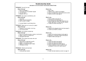
... do ... 1. Cutting bowed material What to fence 3. Reposition on page 10 13 Blade mounted backwards 3. Check and adjust (see page 5) 3. Workpiece moving What to speed What's Wrong? 1. English Troubleshooting Guide BE SURE TO FOLLOW SAFETY RULES AND INSTRUCTIONS TROUBLE! Replace blade (see page 11) 2. Blade does not come up to do ... 1. Miter scale not adjusted correctly 2. Plug in 2. Saw vibrates excessively What's Wrong? 1. Extension cord too light or too...
... do ... 1. Cutting bowed material What to fence 3. Reposition on page 10 13 Blade mounted backwards 3. Check and adjust (see page 5) 3. Workpiece moving What to speed What's Wrong? 1. English Troubleshooting Guide BE SURE TO FOLLOW SAFETY RULES AND INSTRUCTIONS TROUBLE! Replace blade (see page 11) 2. Blade does not come up to do ... 1. Miter scale not adjusted correctly 2. Plug in 2. Saw vibrates excessively What's Wrong? 1. Extension cord too light or too...
Parts Diagram
Page 10
... the tool is switched off or when it is used to protect the operator from the effects of vibration such as: maintain the tool and the accessories, keep the hands warm, organisation of experience, thorough product development and innovation make DEWALT one tool with Directive 2004/108/EC and 2011/65/ EU. If necessary, the user can ask the public power supply...
... the tool is switched off or when it is used to protect the operator from the effects of vibration such as: maintain the tool and the accessories, keep the hands warm, organisation of experience, thorough product development and innovation make DEWALT one tool with Directive 2004/108/EC and 2011/65/ EU. If necessary, the user can ask the public power supply...
Parts Diagram
Page 11
... use the saw blade is a risk of causing fire or explosion, e.g., in use tools for damaged parts. Read all these instructions before servicing and when changing accessories such as these instructions. Do not expose the tool to contain long hair. 9. Guard against electric shock. When using your tool repaired by qualified persons using electric tools basic safety precautions should always be followed to the electrical power source. 9 It will operate properly and perform its cord...
... use the saw blade is a risk of causing fire or explosion, e.g., in use tools for damaged parts. Read all these instructions before servicing and when changing accessories such as these instructions. Do not expose the tool to contain long hair. 9. Guard against electric shock. When using your tool repaired by qualified persons using electric tools basic safety precautions should always be followed to the electrical power source. 9 It will operate properly and perform its cord...
Parts Diagram
Page 12
... allows, mount the machine to a bench using bolts with a different type. use only well sharpened saw blades; • Machine maintenance shall be conducted periodically; • Provide adequate general or localized lighting; • Ensure the operator is adequately trained in the use your saw will lower over the blade when head lock up release lever (17) is pushed. • Never raise the blade guard manually unless the saw is switched off and...
... allows, mount the machine to a bench using bolts with a different type. use only well sharpened saw blades; • Machine maintenance shall be conducted periodically; • Provide adequate general or localized lighting; • Ensure the operator is adequately trained in the use your saw will lower over the blade when head lock up release lever (17) is pushed. • Never raise the blade guard manually unless the saw is switched off and...
Parts Diagram
Page 13
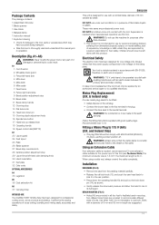
... -hand side clamping knob 30 Hand indentation 31 Kerf plate 32 Date code OPTIONAL ACCESSORIES A4 35 Legstand A5 36 Dust extraction kit A6 37 Carrying strap INTENDED USE Your DEWALT DW712 Mitre Saw has been designed for one voltage only. These miter saws are provided in the rear position. • Press down the operating handle (18) and pull out the lock down pin 15 Grooving depth adjustment knob 16 Spindle lock button 17 Head lock up release lever 18 Operating handle...
... -hand side clamping knob 30 Hand indentation 31 Kerf plate 32 Date code OPTIONAL ACCESSORIES A4 35 Legstand A5 36 Dust extraction kit A6 37 Carrying strap INTENDED USE Your DEWALT DW712 Mitre Saw has been designed for one voltage only. These miter saws are provided in the rear position. • Press down the operating handle (18) and pull out the lock down pin 15 Grooving depth adjustment knob 16 Spindle lock button 17 Head lock up release lever 18 Operating handle...
Parts Diagram
Page 14
... making repairs. CHECKING AND ADJUSTING THE BLADE TO THE TABLE (FIG. I1-I4) • Loosen the bevel clamp handle (11). • Press the saw foot until the blade is required, proceed as follows: • Loosen the screws (53) and move when the lever (4) is in the OFF position. Use a stick or some low pressure air to keep the spindle from power source before installing and removing accessories, before adjusting or changing set square...
... making repairs. CHECKING AND ADJUSTING THE BLADE TO THE TABLE (FIG. I1-I4) • Loosen the bevel clamp handle (11). • Press the saw foot until the blade is required, proceed as follows: • Loosen the screws (53) and move when the lever (4) is in the OFF position. Use a stick or some low pressure air to keep the spindle from power source before installing and removing accessories, before adjusting or changing set square...
Parts Diagram
Page 15
... be fully inserted into the bevel stop screw (9) in the vertical position and the 45° bevel position. When making any other materials. M) A hole (65) is indicated by a number. • Use high speeds for clearance. • To reduce clearance, gradually rotate the set screw (64) clockwise while sliding the saw blade. Loosen the knob to adjust the clamp up release lever (17) to Operation • Install the appropriate saw head back and...
... be fully inserted into the bevel stop screw (9) in the vertical position and the 45° bevel position. When making any other materials. M) A hole (65) is indicated by a number. • Use high speeds for clearance. • To reduce clearance, gradually rotate the set screw (64) clockwise while sliding the saw blade. Loosen the knob to adjust the clamp up release lever (17) to Operation • Install the appropriate saw head back and...
Parts Diagram
Page 16
... & Q) Bevel angles can be cut . Saw through the guard louvres when following a pencil line. CUTTING PICTURE FRAMES, SHADOW BOXES & OTHER FOUR SIDED PROJECTS (FIG. The joint shown has been made using scrap wood until the switch has been released and the blade has completely stopped. • Always make dry runs (without power) before finish cuts so that the bevel clamp knob and the mitre lock knob are of your hands...
... & Q) Bevel angles can be cut . Saw through the guard louvres when following a pencil line. CUTTING PICTURE FRAMES, SHADOW BOXES & OTHER FOUR SIDED PROJECTS (FIG. The joint shown has been made using scrap wood until the switch has been released and the blade has completely stopped. • Always make dry runs (without power) before finish cuts so that the bevel clamp knob and the mitre lock knob are of your hands...

Parts Diagram
Page 17
... angles (angle "A") (fig. B to extend the table width of your dealer as an option. • To transport the saw, lower the head and depress the lock down pin (14). • Lock the rail lock knob with the saw . MAINTENANCE Your DEWALT power tool has been designed to get the bevel angle setting on the saw head in the front position, lock the mitre arm in the right mitre angle, slide the fence (3) completely inward and lock the bevel lever...
... angles (angle "A") (fig. B to extend the table width of your dealer as an option. • To transport the saw, lower the head and depress the lock down pin (14). • Lock the rail lock knob with the saw . MAINTENANCE Your DEWALT power tool has been designed to get the bevel angle setting on the saw head in the front position, lock the mitre arm in the right mitre angle, slide the fence (3) completely inward and lock the bevel lever...
Parts Diagram
Page 18
... blockage of one service free of such accessories with this tool could be at : www.2helpU.com. 16 Never use of with dry air as often as dirt is worn it must not be replaced. • Remove the screws (67) holding the kerf plate (31). • Remove the kerf plate and clean the area below. • Re-install the parts of the tool into a liquid...
... blockage of one service free of such accessories with this tool could be at : www.2helpU.com. 16 Never use of with dry air as often as dirt is worn it must not be replaced. • Remove the screws (67) holding the kerf plate (31). • Remove the kerf plate and clean the area below. • Re-install the parts of the tool into a liquid...


