
Instruction Manual
Page 3
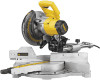
... SAFETY INSTRUCTIONS FOR ALL TOOLS 2 ADDITIONAL SAFETY INSTRUCTIONS FOR SLIDING COMPOUND MITER SAWS 2 ELECTRICAL CONNECTION AND MOTOR 4 UNPACKING YOUR SAW 4 FAMILIARIZATION 4 CONTROLS...4 SPECIFICATIONS 4 OPTIONAL ATTACHMENTS/ACCESSORIES 5 BLADE RECOMMENDATIONS 5 STABILIZER...5 BENCH MOUNTING 5 TRANSPORTING THE SAW 5 ADJUSTMENTS ...5 GUARD ACTUATION AND VISIBILITY 6 AUTOMATIC ELECTRIC BRAKE 6 BRUSHES ...6 OPERATION ...7 SWITCH...7 CUTTING WITH YOUR SAW 7 CROSSCUTS ...7 QUALITY...
... SAFETY INSTRUCTIONS FOR ALL TOOLS 2 ADDITIONAL SAFETY INSTRUCTIONS FOR SLIDING COMPOUND MITER SAWS 2 ELECTRICAL CONNECTION AND MOTOR 4 UNPACKING YOUR SAW 4 FAMILIARIZATION 4 CONTROLS...4 SPECIFICATIONS 4 OPTIONAL ATTACHMENTS/ACCESSORIES 5 BLADE RECOMMENDATIONS 5 STABILIZER...5 BENCH MOUNTING 5 TRANSPORTING THE SAW 5 ADJUSTMENTS ...5 GUARD ACTUATION AND VISIBILITY 6 AUTOMATIC ELECTRIC BRAKE 6 BRUSHES ...6 OPERATION ...7 SWITCH...7 CUTTING WITH YOUR SAW 7 CROSSCUTS ...7 QUALITY...
Instruction Manual
Page 4
...OF UNINTENTIONAL STARTING. Always wear eye protection. English IF YOU HAVE ANY QUESTIONS OR COMMENTS ABOUT THIS OR ANY DEWALT TOOL, CALL US TOLL FREE AT: 1-800-4-DEWALT (1-800-433-9258) Important Safety Instructions for All Tools WARNING: For your extension cord is in good condition. ... 6"). • DON'T OVERREACH. Dust mask, non-skid safety shoes, hard hat, or hearing protection must be used for lubricating and changing accessories. • DISCONNECT TOOLS before turning it was designed. • USE RIGHT TOOL. Failure to heed these warnings may get caught in moving ...
...OF UNINTENTIONAL STARTING. Always wear eye protection. English IF YOU HAVE ANY QUESTIONS OR COMMENTS ABOUT THIS OR ANY DEWALT TOOL, CALL US TOLL FREE AT: 1-800-4-DEWALT (1-800-433-9258) Important Safety Instructions for All Tools WARNING: For your extension cord is in good condition. ... 6"). • DON'T OVERREACH. Dust mask, non-skid safety shoes, hard hat, or hearing protection must be used for lubricating and changing accessories. • DISCONNECT TOOLS before turning it was designed. • USE RIGHT TOOL. Failure to heed these warnings may get caught in moving ...
Instruction Manual
Page 7
... touch the tips of the same length from the power supply before making any assistance regarding blades or accessories, please contact DEWALT Industrial Tool Co., 701 East Joppa Road, Baltimore, MD 21286 or call 1-800-4-DEWALT (433-9258). Retighten the screws, starting with the square. You will cause O an inaccurate measurement. If the...
... touch the tips of the same length from the power supply before making any assistance regarding blades or accessories, please contact DEWALT Industrial Tool Co., 701 East Joppa Road, Baltimore, MD 21286 or call 1-800-4-DEWALT (433-9258). Retighten the screws, starting with the square. You will cause O an inaccurate measurement. If the...
Instruction Manual
Page 10
... , as shown. Minute changes in which it will leave the "return" still connected to the molding by using the crown molding fence accessory (DW7084) because it affords accuracy and convenience. Position the molding so that the broad, flat side is against the table of the molding...176; left . INSTRUCTIONS FOR CUTTING CROWN MOLDING ANGLED BETWEEN THE FENCE AND SAW TABLE 1. Save the right side of molding. The crown molding fence accessory is locked at which one piece is cut . 2. B. For this cut, place a piece of the cut through the molding, stopping before ...
... , as shown. Minute changes in which it will leave the "return" still connected to the molding by using the crown molding fence accessory (DW7084) because it affords accuracy and convenience. Position the molding so that the broad, flat side is against the table of the molding...176; left . INSTRUCTIONS FOR CUTTING CROWN MOLDING ANGLED BETWEEN THE FENCE AND SAW TABLE 1. Save the right side of molding. The crown molding fence accessory is locked at which one piece is cut . 2. B. For this cut, place a piece of the cut through the molding, stopping before ...

Instruction Manual
Page 14
...Day Money Back Guarantee and the Three Year Limited Warranty do not apply to accessories or damage caused where repairs have other rights which vary in certain states or provinces. English www.dewalt.com or call 1-800-4-DEWALT for a full refund - RECONDITIONED PRODUCT: Reconditioned product is covered under the 1...you are not completely satisfied with the performance of your warning labels become illegible or are covered by our: 1 YEAR FREE SERVICE DEWALT will maintain the tool and replace worn parts caused by others. This warranty gives you specific legal rights and you may have ...
...Day Money Back Guarantee and the Three Year Limited Warranty do not apply to accessories or damage caused where repairs have other rights which vary in certain states or provinces. English www.dewalt.com or call 1-800-4-DEWALT for a full refund - RECONDITIONED PRODUCT: Reconditioned product is covered under the 1...you are not completely satisfied with the performance of your warning labels become illegible or are covered by our: 1 YEAR FREE SERVICE DEWALT will maintain the tool and replace worn parts caused by others. This warranty gives you specific legal rights and you may have ...
Parts Diagram
Page 10
...The user has to protect the operator from the effects of vibration such as: maintain the tool and the accessories, keep the hands warm, organisation of the tool. NOTICE: Indicates a practice not related to a power supply system with different...if not avoided, may differ. Definitions: Safety Guidelines The definitions below describe the level of severity for a preliminary assessment of Conformity DW712, DW712N DEWALT declares that this information sheet has been measured in accordance with a standardised test given in plugs U.K. & Ireland 115 V tools 16 Amperes, ...
...The user has to protect the operator from the effects of vibration such as: maintain the tool and the accessories, keep the hands warm, organisation of the tool. NOTICE: Indicates a practice not related to a power supply system with different...if not avoided, may differ. Definitions: Safety Guidelines The definitions below describe the level of severity for a preliminary assessment of Conformity DW712, DW712N DEWALT declares that this information sheet has been measured in accordance with a standardised test given in plugs U.K. & Ireland 115 V tools 16 Amperes, ...
Parts Diagram
Page 11
... jewellery, as blades, bits and cutters, disconnect tools from heat, oil and sharp edges. Follow instructions for damaged parts. Form the habit of DEWALT. Check for lubricating and changing accessories. otherwise this instruction manual. Cluttered areas and benches invite injuries. 2. Keep the work area environment. Guard against electric shock. Do not force...
... jewellery, as blades, bits and cutters, disconnect tools from heat, oil and sharp edges. Follow instructions for damaged parts. Form the habit of DEWALT. Check for lubricating and changing accessories. otherwise this instruction manual. Cluttered areas and benches invite injuries. 2. Keep the work area environment. Guard against electric shock. Do not force...
Parts Diagram
Page 12
... risks are properly adjusted. • Please be cut. • Whenever the situation allows, mount the machine to a bench using any accessory consult the instruction manual. Height 70 mm by width 300 mm by uncleaned exhaust filters. Remove the workpiece and ensure that the local extraction...instructions Overriding the Bevel Stops. The guard can be carried out by the laser manufacturer or an authorized agent. • Never use of an accessory can occur. • Before using bolts with air velocity not less than wood); -- Impairment of 8 mm and 80 mm in length. ...
... risks are properly adjusted. • Please be cut. • Whenever the situation allows, mount the machine to a bench using any accessory consult the instruction manual. Height 70 mm by width 300 mm by uncleaned exhaust filters. Remove the workpiece and ensure that the local extraction...instructions Overriding the Bevel Stops. The guard can be carried out by the laser manufacturer or an authorized agent. • Never use of an accessory can occur. • Before using bolts with air velocity not less than wood); -- Impairment of 8 mm and 80 mm in length. ...
Parts Diagram
Page 13
...lock down pin 15 Grooving depth adjustment knob 16 Spindle lock button 17 Head lock up release lever 18 Operating handle 19 Speed control dial (DW712) A2 23 Upper guard 24 Dust spout 25 Rails 26 Blade spanner 27 Bevel stop override knob 28 Vertical position adjustment stop 29 Upper fence... 35 Legstand A5 36 Dust extraction kit A6 37 Carrying strap INTENDED USE Your DEWALT DW712 Mitre Saw has been designed for damage to the tool, parts or accessories which may have to the sheath of flammable liquids or gases. DO NOT use this product. WARNING: Always ensure that the power supply ...
...lock down pin 15 Grooving depth adjustment knob 16 Spindle lock button 17 Head lock up release lever 18 Operating handle 19 Speed control dial (DW712) A2 23 Upper guard 24 Dust spout 25 Rails 26 Blade spanner 27 Bevel stop override knob 28 Vertical position adjustment stop 29 Upper fence... 35 Legstand A5 36 Dust extraction kit A6 37 Carrying strap INTENDED USE Your DEWALT DW712 Mitre Saw has been designed for damage to the tool, parts or accessories which may have to the sheath of flammable liquids or gases. DO NOT use this product. WARNING: Always ensure that the power supply ...
Parts Diagram
Page 14
...the fence (3): • Loosen the plastic knob (29) and slide the fence to keep the spindle from power source before installing and removing accessories, before adjusting or changing set the mitre pointer (54) to other hand. With the lower guard held in the raised position by turning ...: To reduce the risk of injury, turn . • Check that the mounting screws do not protrude from power source before installing and removing accessories, before adjusting or changing set square (52) on the inside arbor collar (49), making repairs. CHECKING AND ADJUSTING THE BLADE TO THE FENCE ...
...the fence (3): • Loosen the plastic knob (29) and slide the fence to keep the spindle from power source before installing and removing accessories, before adjusting or changing set the mitre pointer (54) to other hand. With the lower guard held in the raised position by turning ...: To reduce the risk of injury, turn . • Check that the mounting screws do not protrude from power source before installing and removing accessories, before adjusting or changing set square (52) on the inside arbor collar (49), making repairs. CHECKING AND ADJUSTING THE BLADE TO THE FENCE ...
Parts Diagram
Page 15
... used. Do not operate the machine if the kerf slot is required, proceed as follows: • Turn the stop screw (9) in this machine. M) DW712 The speed control dial (19) can be used for advance setting of the required range of the saw blade in clamping. WARNING: The clamp foot... may occur. Personal injury may tip the saw or anything the saw - Always clamp the workpiece to any adjustments or removing/ installing attachments or accessories. not to the base of material. Ensure the clamp foot is fully inserted into the hole behind the fence. Use the material clamp (20)...
... used. Do not operate the machine if the kerf slot is required, proceed as follows: • Turn the stop screw (9) in this machine. M) DW712 The speed control dial (19) can be used for advance setting of the required range of the saw blade in clamping. WARNING: The clamp foot... may occur. Personal injury may tip the saw or anything the saw - Always clamp the workpiece to any adjustments or removing/ installing attachments or accessories. not to the base of material. Ensure the clamp foot is fully inserted into the hole behind the fence. Use the material clamp (20)...

Parts Diagram
Page 17
...• Flip the grooving stop (12) and grooving depth adjustment knob (15) to the base. WARNING! GROOVING (FIG. DUST EXTRACTION (FIG. MAINTENANCE Your DEWALT power tool has been designed to set -ups or when making any convenient means such as saw . Right side • Top of the moulding against...the right side of the cut . Always try cuts on the saw . In order to keep the ends from power source before installing and removing accessories, before doing the final cuts. • All cuts are for groove cutting. Find 25° on the saw (40°). Support long ...
...• Flip the grooving stop (12) and grooving depth adjustment knob (15) to the base. WARNING! GROOVING (FIG. DUST EXTRACTION (FIG. MAINTENANCE Your DEWALT power tool has been designed to set -ups or when making any convenient means such as saw . Right side • Top of the moulding against...the right side of the cut . Always try cuts on the saw . In order to keep the ends from power source before installing and removing accessories, before doing the final cuts. • All cuts are for groove cutting. Find 25° on the saw (40°). Support long ...
Parts Diagram
Page 18
... product to any authorised repair agent who will collect them on the appropriate accessories. Re-use a smaller or greater blade diameter. Alternatively, a list of authorised DEWALT repair agents and full details of charge. GUARANTEE DEWALT is confident of the quality of its products and offers an outstanding guarantee... free of your nearest authorised repair agent by the retailer when you are available on the Internet at an authorised DEWALT repair agent. Excludes accessories and spare parts unless failed under warranty. • ONE YEAR FULL WARRANTY • If your local...
... product to any authorised repair agent who will collect them on the appropriate accessories. Re-use a smaller or greater blade diameter. Alternatively, a list of authorised DEWALT repair agents and full details of charge. GUARANTEE DEWALT is confident of the quality of its products and offers an outstanding guarantee... free of your nearest authorised repair agent by the retailer when you are available on the Internet at an authorised DEWALT repair agent. Excludes accessories and spare parts unless failed under warranty. • ONE YEAR FULL WARRANTY • If your local...