Operating Instructions
Page 2
... itself, not the speakers. Address: 16450 W. Telephone Number: 858-942-2230 This device complies with Part 15 of Conformity Trade Name: SONY Model: FWD-42PV1/42PV1P/42PV1A Responsible Party: Sony Electronics Inc. This equipment generates, uses, and can radiate radio frequency energy and, if not installed ...the user is connected. • Consult the dealer or an experienced radio/TV technician for a Class B digital device, pursuant to Part 15 of the following two conditions: (1) This device may cause undesired operation. WARNING Owner's Record The model and serial numbers are ...
... itself, not the speakers. Address: 16450 W. Telephone Number: 858-942-2230 This device complies with Part 15 of Conformity Trade Name: SONY Model: FWD-42PV1/42PV1P/42PV1A Responsible Party: Sony Electronics Inc. This equipment generates, uses, and can radiate radio frequency energy and, if not installed ...the user is connected. • Consult the dealer or an experienced radio/TV technician for a Class B digital device, pursuant to Part 15 of the following two conditions: (1) This device may cause undesired operation. WARNING Owner's Record The model and serial numbers are ...
Operating Instructions
Page 3
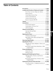
Table of Contents Precautions 5 (GB) Location and Function of Parts and Controls ....... 7 (GB) Front / Rear / Left side / Right side / Bottom .......... 7 (GB) Indicator Section 8 (GB) Control Button Section (Top 8 (GB) Connector Panel (Bottom 9 (GB) Connector Panel (Left side 10 (GB) Remote Commander RM-980 12 (GB) Caution 14 (GB) Connections 15 (GB) Connecting the Speakers...
Table of Contents Precautions 5 (GB) Location and Function of Parts and Controls ....... 7 (GB) Front / Rear / Left side / Right side / Bottom .......... 7 (GB) Indicator Section 8 (GB) Control Button Section (Top 8 (GB) Connector Panel (Bottom 9 (GB) Connector Panel (Left side 10 (GB) Remote Commander RM-980 12 (GB) Caution 14 (GB) Connections 15 (GB) Connecting the Speakers...
Operating Instructions
Page 5
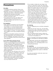
...is manufactured with extremely high precision technology, it as at high altitudes, a buzzing or humming noise may emanate from the unit. On the PDP (Plasma Display Panel) • You may damage the finish of these operations, wait about 5 seconds before cleaning the display. • Gently wipe off grimy stains... stand. If you install the unit on the screen for a long period of time, part of the way it will never completely disappear. • To protect the plasma display, this unit, contact your authorized Sony dealers. 5 (GB) Never pull the cord itself. • When you have it ...
...is manufactured with extremely high precision technology, it as at high altitudes, a buzzing or humming noise may emanate from the unit. On the PDP (Plasma Display Panel) • You may damage the finish of these operations, wait about 5 seconds before cleaning the display. • Gently wipe off grimy stains... stand. If you install the unit on the screen for a long period of time, part of the way it will never completely disappear. • To protect the plasma display, this unit, contact your authorized Sony dealers. 5 (GB) Never pull the cord itself. • When you have it ...
Operating Instructions
Page 7
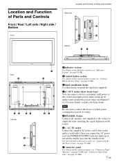
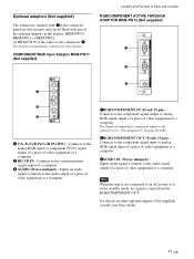
...the connector panel, see "Control Button Section (Top)" on page 8 (GB). 3Stand installation hooks Use these hooks to install the stand (not supplied). 4AC OUT socket (three brade type) You can connect a device consuming small power to a wall outlet. For more details, consult your Sony dealer....power cord, the POWER/STANDBY indicator lights up an audio/visual system (the power rating: maximum 0.5 A). Note Be sure not to connect the device of Parts and Controls Right side 4 5 SPEAKER R Bottom 67 Rear 2 45 Left side 67 7 5 1 3 57 1Indicator section For details on the Indicator ...
...the connector panel, see "Control Button Section (Top)" on page 8 (GB). 3Stand installation hooks Use these hooks to install the stand (not supplied). 4AC OUT socket (three brade type) You can connect a device consuming small power to a wall outlet. For more details, consult your Sony dealer....power cord, the POWER/STANDBY indicator lights up an audio/visual system (the power rating: maximum 0.5 A). Note Be sure not to connect the device of Parts and Controls Right side 4 5 SPEAKER R Bottom 67 Rear 2 45 Left side 67 7 5 1 3 57 1Indicator section For details on the Indicator ...
Operating Instructions
Page 8
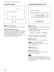
...select a signal to turn the unit ON/STANDBY. When the POWER/STANDBY indicator blinks, see "Selfdiagnosis Function" on . Note To protect the panel, a certain amount of time is not installed in the OPTION1 slot, OPTION1 will be input from a computer. Press again to return to...the standby mode. Wait about 5 seconds after one of these operations before executing the next operation. 8 (GB) Location and Function of Parts and Controls Indicator Section Control Button Section (Top) 12 12345 6 1Remote control detector Receives the signals from the Remote Commander. 2POWER/STANDBY indicator...
...select a signal to turn the unit ON/STANDBY. When the POWER/STANDBY indicator blinks, see "Selfdiagnosis Function" on . Note To protect the panel, a certain amount of time is not installed in the OPTION1 slot, OPTION1 will be input from a computer. Press again to return to...the standby mode. Wait about 5 seconds after one of these operations before executing the next operation. 8 (GB) Location and Function of Parts and Controls Indicator Section Control Button Section (Top) 12 12345 6 1Remote control detector Receives the signals from the Remote Commander. 2POWER/STANDBY indicator...
Operating Instructions
Page 9
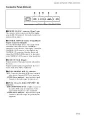
For details, contact your authorized Sony dealers. 2CONTROL S IN/OUT (Control S Signal Input/ Output) Connector (Minijack) You can control multiple devices with a single remote commander when connected to the CONTROL S connector ... : Connects to the audio output of a piece of video devices. Connects to the digital RGB signal output of video equipment. 9 (GB) Connector Panel (Bottom) 1 23 4 Location and Function of Parts and Controls 5 AC IN REMOTE IN OUT R L AUDIO CONTROL S AUDIO OUT DVI-HDCP INPUT 1 AUDIO RGB/COMPONENT INPUT 2 1REMOTE (RS-232C) connector...
For details, contact your authorized Sony dealers. 2CONTROL S IN/OUT (Control S Signal Input/ Output) Connector (Minijack) You can control multiple devices with a single remote commander when connected to the CONTROL S connector ... : Connects to the audio output of a piece of video devices. Connects to the digital RGB signal output of video equipment. 9 (GB) Connector Panel (Bottom) 1 23 4 Location and Function of Parts and Controls 5 AC IN REMOTE IN OUT R L AUDIO CONTROL S AUDIO OUT DVI-HDCP INPUT 1 AUDIO RGB/COMPONENT INPUT 2 1REMOTE (RS-232C) connector...
Operating Instructions
Page 10
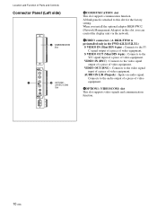
... (Mini DIN 4-pin) : Connects to the audio output of a piece of video equipment. A blank panel is attached to this slot, you install the optional adaptor BKM-FW32 (Network Management Adaptor) in the FWD-42LX1/32LX1.) S VIDEO IN (Mini DIN 4-pin) : Connects to the Y/ C signal output of ...a piece of video equipment. VIDEO OUT (BNC) : Connects to the video signal output of a piece of video equipment. VIDEO IN (BNC) : Connects to the video signal input of a piece of Parts and Controls Connector Panel...
... (Mini DIN 4-pin) : Connects to the audio output of a piece of video equipment. A blank panel is attached to this slot, you install the optional adaptor BKM-FW32 (Network Management Adaptor) in the FWD-42LX1/32LX1.) S VIDEO IN (Mini DIN 4-pin) : Connects to the Y/ C signal output of ...a piece of video equipment. VIDEO OUT (BNC) : Connects to the video signal output of a piece of video equipment. VIDEO IN (BNC) : Connects to the video signal input of a piece of Parts and Controls Connector Panel...
Operating Instructions
Page 11
.... Note When the unit is output from the RGB/COMPONENT OUT. COMPONENT/RGB Input Adaptor BKM-FW11 (Not supplied) Location and Function of Parts and Controls RGB/COMPONENT ACTIVE THROUGH ADAPTOR BKM-FW12 (Not supplied) 1 2 IN RGB/COMPONENT THROUGH OUT AUDIO IN Y/G COMPONENT/RGB INPUT ADAPTOR... on inputting a component signal to the connector, see "Pin assignment" on installation, consult your Sony dealer. 11 (GB) Optional adaptors (Not supplied) The connectors marked with 7on the connector panel are slot-in types and can be fitted with any of video equipment or a computer. 3AUDIO...
.... Note When the unit is output from the RGB/COMPONENT OUT. COMPONENT/RGB Input Adaptor BKM-FW11 (Not supplied) Location and Function of Parts and Controls RGB/COMPONENT ACTIVE THROUGH ADAPTOR BKM-FW12 (Not supplied) 1 2 IN RGB/COMPONENT THROUGH OUT AUDIO IN Y/G COMPONENT/RGB INPUT ADAPTOR... on inputting a component signal to the connector, see "Pin assignment" on installation, consult your Sony dealer. 11 (GB) Optional adaptors (Not supplied) The connectors marked with 7on the connector panel are slot-in types and can be fitted with any of video equipment or a computer. 3AUDIO...
Operating Instructions
Page 12
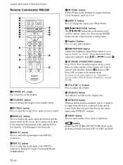
... Press to select the signal input to the INPUT1 connectors. 6INPUT2 button Press to select the signal input to hide them. Location and Function of Parts and Controls Remote Commander RM-980 1 2 MUTING DISPLAY STBY ON 3 4 5 qf 6 qg 7 qh 8 qj 9 ENTER 123 0 456 789 qa 0 qk qs ON SET qd ql...
... Press to select the signal input to the INPUT1 connectors. 6INPUT2 button Press to select the signal input to hide them. Location and Function of Parts and Controls Remote Commander RM-980 1 2 MUTING DISPLAY STBY ON 3 4 5 qf 6 qg 7 qh 8 qj 9 ENTER 123 0 456 789 qa 0 qk qs ON SET qd ql...
Operating Instructions
Page 13
qk CHROMA button Adjusts the chroma when the picture mode is set to any of "User1" to "User3." Press this button and adjust the chroma with the M/m or
qk CHROMA button Adjusts the chroma when the picture mode is set to any of "User1" to "User3." Press this button and adjust the chroma with the M/m or
Operating Instructions
Page 21
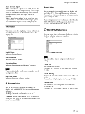
...Off Timer Select Set ENTER Exit MENU Model Name Indicates the model name. For details, see "Setting an IP Address and communication speed" on page 42 (GB). Auto Screen Adjust When "Auto Screen Adjust" is set disabled. For details, see "Adjusting the time and the day" on the ...saves the screen-settings for size and positioning for displaying various information, including information on or off at which the power is not counted as part of operation. TIMER/CLOCK menu You can set to Off, this auto adjustment is set the timer, adjust time, display the built-in ...
...Off Timer Select Set ENTER Exit MENU Model Name Indicates the model name. For details, see "Setting an IP Address and communication speed" on page 42 (GB). Auto Screen Adjust When "Auto Screen Adjust" is set disabled. For details, see "Adjusting the time and the day" on the ...saves the screen-settings for size and positioning for displaying various information, including information on or off at which the power is not counted as part of operation. TIMER/CLOCK menu You can set to Off, this auto adjustment is set the timer, adjust time, display the built-in ...


