Operating Instructions
Page 2
... that any interference received, including interference that interference will not occur in a residential installation. For customers in the U.S.A. WARNING Owner's Record The model and serial numbers are located on a circuit different from that to which can be easily accessible. For customers in Canada This class B digital apparatus complies with the instructions, may cause undesired operation. Sony Customer Information Services Center 1-800...
... that any interference received, including interference that interference will not occur in a residential installation. For customers in the U.S.A. WARNING Owner's Record The model and serial numbers are located on a circuit different from that to which can be easily accessible. For customers in Canada This class B digital apparatus complies with the instructions, may cause undesired operation. Sony Customer Information Services Center 1-800...
Operating Instructions
Page 3
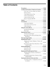
...) Control Button Section (Top 8 (GB) Connector Panel (Bottom 9 (GB) Connector Panel (Left side 10 (GB) Remote Commander RM-980 12 (GB) Caution 14 (GB) Connections 15 (GB) Connecting the Speakers 15 (GB) Connecting the AC Power Cord 15 (GB) Cable management 16 (GB) Using On-screen Menus 17 (GB) Operating Through Menus 17 (GB) GB Menu Guide 17 (GB) Watching the Picture 23 (GB) Switching the Input Signal 23 (GB) Input Signal, Picture Mode...
...) Control Button Section (Top 8 (GB) Connector Panel (Bottom 9 (GB) Connector Panel (Left side 10 (GB) Remote Commander RM-980 12 (GB) Caution 14 (GB) Connections 15 (GB) Connecting the Speakers 15 (GB) Connecting the AC Power Cord 15 (GB) Cable management 16 (GB) Using On-screen Menus 17 (GB) Operating Through Menus 17 (GB) GB Menu Guide 17 (GB) Watching the Picture 23 (GB) Switching the Input Signal 23 (GB) Input Signal, Picture Mode...
Operating Instructions
Page 5
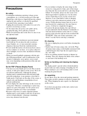
... plasma display panel is used for a long period of time, part of time after the unit has been switched ON/ STANDBY. Use the screen saver function to display the same image on the floor, be sure to unplug the power cord before cleaning the display. • Gently wipe off grimy stains using a cloth slightly moistened with low air pressure, such as malfunction of the Remote Commander, noisy picture, noisy sound...
... plasma display panel is used for a long period of time, part of time after the unit has been switched ON/ STANDBY. Use the screen saver function to display the same image on the floor, be sure to unplug the power cord before cleaning the display. • Gently wipe off grimy stains using a cloth slightly moistened with low air pressure, such as malfunction of the Remote Commander, noisy picture, noisy sound...
Operating Instructions
Page 7
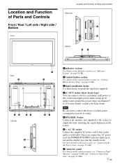
... Parts and Controls Front / Rear / Left side / Right side / Bottom Front AC OUT Location and Function of which power consumption exceeds its rating. 5SPEAKER Socket Connects the speakers (not supplied) to this socket and supply power when setting up in red and the display goes into the standby mode. Once you connect the AC power cord, the POWER/STANDBY indicator lights up an audio/visual system (the power rating: maximum 0.5 A). AC IN socket Connect the supplied...
... Parts and Controls Front / Rear / Left side / Right side / Bottom Front AC OUT Location and Function of which power consumption exceeds its rating. 5SPEAKER Socket Connects the speakers (not supplied) to this socket and supply power when setting up in red and the display goes into the standby mode. Once you connect the AC power cord, the POWER/STANDBY indicator lights up an audio/visual system (the power rating: maximum 0.5 A). AC IN socket Connect the supplied...
Operating Instructions
Page 9
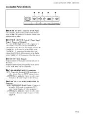
... audio of video equipment. Outputs an audio signal corresponding to the Active Picture while in the P&P or PinP mode. 4INPUT1 (DIGITAL RGB IN) connectors DVI : Connects to the audio output of a piece of video devices. AUDIO (Stereo minijack) : Inputs an audio signal. Connects to the digital RGB signal output of video equipment. 9 (GB) Connect the CONTROL S OUT connector on this display to the CONTROL S IN connector of the other device, and connect the CONTROL S IN connector on the screen. Supports...
... audio of video equipment. Outputs an audio signal corresponding to the Active Picture while in the P&P or PinP mode. 4INPUT1 (DIGITAL RGB IN) connectors DVI : Connects to the audio output of a piece of video devices. AUDIO (Stereo minijack) : Inputs an audio signal. Connects to the digital RGB signal output of video equipment. 9 (GB) Connect the CONTROL S OUT connector on this display to the CONTROL S IN connector of the other device, and connect the CONTROL S IN connector on the screen. Supports...
Operating Instructions
Page 10
... video equipment. AUDIO IN L/R (Pinjack) : Inputs an audio signal. Connects to the video signal output of a piece of video equipment. Location and Function of video equipment. 8OPTION1 (VIDEO/COM) slot This slot supports video signals and communication function. SPEAKER L 10 (GB) A blank panel is preinstalled only in the FWD-42LX1/32LX1.) S VIDEO IN (Mini DIN 4-pin) : Connects to the Y/C signal input of a piece of video equipment. VIDEO IN (BNC) : Connects to the audio output of a piece of Parts and Controls...
... video equipment. AUDIO IN L/R (Pinjack) : Inputs an audio signal. Connects to the video signal output of a piece of video equipment. Location and Function of video equipment. 8OPTION1 (VIDEO/COM) slot This slot supports video signals and communication function. SPEAKER L 10 (GB) A blank panel is preinstalled only in the FWD-42LX1/32LX1.) S VIDEO IN (Mini DIN 4-pin) : Connects to the Y/C signal input of a piece of video equipment. VIDEO IN (BNC) : Connects to the audio output of a piece of Parts and Controls...
Operating Instructions
Page 11
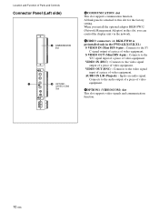
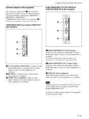
... details on installation, consult your Sony dealer. 11 (GB) Connects to an AC power or is in the display; AUDIO VD 1RGB/COMPONENT IN (D-sub 15-pin) : Connects to the component signal input or analog RGB signal input of a piece of video equipment or a computer. 3AUDIO IN (Stereo minijack) : Inputs audio signal. Optional adaptors (Not supplied) The connectors marked with 7on the connector panel are slot-in...
... details on installation, consult your Sony dealer. 11 (GB) Connects to an AC power or is in the display; AUDIO VD 1RGB/COMPONENT IN (D-sub 15-pin) : Connects to the component signal input or analog RGB signal input of a piece of video equipment or a computer. 3AUDIO IN (Stereo minijack) : Inputs audio signal. Optional adaptors (Not supplied) The connectors marked with 7on the connector panel are slot-in...
Operating Instructions
Page 12
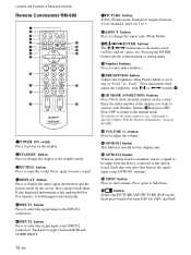
... of Parts and Controls Remote Commander RM-980 1 2 MUTING DISPLAY STBY ON 3 4 5 qf 6 qg 7 qh 8 qj 9 ENTER 123 0 456 789 qa 0 qk qs ON SET qd ql MONITOR RM-980 1POWER ON switch Press to power on the screen. Press again to restore sound. 4DISPLAY button Press to display the input signal information and the picture mode on the display. 2STANDBY button Press to change the display to the standby mode. 3MUTING button...
... of Parts and Controls Remote Commander RM-980 1 2 MUTING DISPLAY STBY ON 3 4 5 qf 6 qg 7 qh 8 qj 9 ENTER 123 0 456 789 qa 0 qk qs ON SET qd ql MONITOR RM-980 1POWER ON switch Press to power on the screen. Press again to restore sound. 4DISPLAY button Press to display the input signal information and the picture mode on the display. 2STANDBY button Press to change the display to the standby mode. 3MUTING button...
Operating Instructions
Page 15
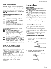
... 4:3 video source (conventional TV broadcast) 3 Video game sources 4 DVD on-screen menu displays 5 On-screen menus, channel numbers, etc., of "SCREEN SAVER" If the displayed image appears as DSS, Cable box, video decks, etc. Precautions to a normal image, select "Off" or reset the specified time in "Auto." However, the burn-in or after image reduction. To return to avoid/reduce burn-in and picture retention A Use the SCREEN SAVER function. Never pull the cable itself. • Refer to the instruction manual...
... 4:3 video source (conventional TV broadcast) 3 Video game sources 4 DVD on-screen menu displays 5 On-screen menus, channel numbers, etc., of "SCREEN SAVER" If the displayed image appears as DSS, Cable box, video decks, etc. Precautions to a normal image, select "Off" or reset the specified time in "Auto." However, the burn-in or after image reduction. To return to avoid/reduce burn-in and picture retention A Use the SCREEN SAVER function. Never pull the cable itself. • Refer to the instruction manual...

Operating Instructions
Page 18
Note You cannot adjust the following items when Picture Mode is used for horizontal and vertical display, and automatically expands the picture to "Vivid" or "Standard." PICTURE AND PICTURE(PAP) PAP: Off Active Picture Picture Size Picture Position Select Set ENTER Exit MENU For details, see "Setting the Aspect" on page 33 (GB). Wide Setup Sets the Auto Wide function. SCREEN CONTROL menu You can make settings for connecting multiple display units and forming a video wall in a 2 ×...
Note You cannot adjust the following items when Picture Mode is used for horizontal and vertical display, and automatically expands the picture to "Vivid" or "Standard." PICTURE AND PICTURE(PAP) PAP: Off Active Picture Picture Size Picture Position Select Set ENTER Exit MENU For details, see "Setting the Aspect" on page 33 (GB). Wide Setup Sets the Auto Wide function. SCREEN CONTROL menu You can make settings for connecting multiple display units and forming a video wall in a 2 ×...
Operating Instructions
Page 19
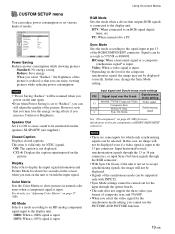
... mode when a device that case, change the Sync Mode setting. In that outputs RGB signals is connected to "Reduce", you can be displayed even if a video signal is not set to the display unit. Input horizontal/vertical synchronization signals through the 13 or 14 pin connectors, or input Sync On Green signals through the option boards. • This unit does not support the three value sync format of modes. CUSTOM SETUP Power Saving: Speaker Out: Closed Caption: Display: Color Matrix: HD Mode: RGB Mode: Sync Mode: Remote...
... mode when a device that case, change the Sync Mode setting. In that outputs RGB signals is connected to "Reduce", you can be displayed even if a video signal is not set to the display unit. Input horizontal/vertical synchronization signals through the 13 or 14 pin connectors, or input Sync On Green signals through the option boards. • This unit does not support the three value sync format of modes. CUSTOM SETUP Power Saving: Speaker Out: Closed Caption: Display: Color Matrix: HD Mode: RGB Mode: Sync Mode: Remote...
Operating Instructions
Page 20
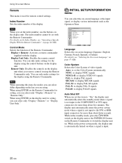
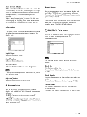
... Operation Time. Display + Remote: Activates a remote commander supplied with the Remote Commander. INITIAL SETUP/INFORMATION Language: Color System: Auto Shut Off: Auto Screen Adjust: Information IP Address Setup Speed Setup English Auto Off On Select Set ENTER Exit MENU Language Selects the on . Note When you set with the display. INITIAL SETUP/INFORMATION menu You can only make settings for the display using the Remote Commander only. While in the power saving mode, the display unit is automatically turned...
... Operation Time. Display + Remote: Activates a remote commander supplied with the Remote Commander. INITIAL SETUP/INFORMATION Language: Color System: Auto Shut Off: Auto Screen Adjust: Information IP Address Setup Speed Setup English Auto Off On Select Set ENTER Exit MENU Language Selects the on . Note When you set with the display. INITIAL SETUP/INFORMATION menu You can only make settings for the display using the Remote Commander only. While in the power saving mode, the display unit is automatically turned...
Operating Instructions
Page 21
... Exit MENU Model Name Indicates the model name. Select Set ENTER Exit MENU Note The time and the day are switched, the original factory settings operate. Operation Time Indicates the total number of hours of the display unit. Manual: Manual configuration to Off, this auto adjustment is set disabled. Clock Set Sets the time and the day. On/Off Timer Sets the time at a predetermined time. When "Auto Screen Adjust" is set to set an IP address. Even when input signals...
... Exit MENU Model Name Indicates the model name. Select Set ENTER Exit MENU Note The time and the day are switched, the original factory settings operate. Operation Time Indicates the total number of hours of the display unit. Manual: Manual configuration to Off, this auto adjustment is set disabled. Clock Set Sets the time and the day. On/Off Timer Sets the time at a predetermined time. When "Auto Screen Adjust" is set to set an IP address. Even when input signals...
Operating Instructions
Page 23
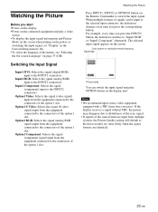
... format are input from multiple systems, the Picture Quality setting will default to the most recently set "Display" in the Custom Setup menu to the connectors of the menus, see "Selecting the On-screen Language" on page 37 (GB). Watching the Picture Before you start • Power on the display. • Power on the connected equipment and play a video source. • To display the input signal information and Picture Mode on the screen when turning...
... format are input from multiple systems, the Picture Quality setting will default to the most recently set "Display" in the Custom Setup menu to the connectors of the menus, see "Selecting the On-screen Language" on page 37 (GB). Watching the Picture Before you start • Power on the display. • Power on the connected equipment and play a video source. • To display the input signal information and Picture Mode on the screen when turning...
Operating Instructions
Page 24
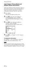
Note You can display the input signal information and the time anytime by pressing the DISPLAY button on or when the input signal is switched. Watching the Picture Input Signal, Picture Mode and Display Status Information Input signal and Picture Mode information appear on the screen for about five seconds when the power is turned on the Remote Commander, regardless of the above , then press ENTER. To display the information Set "Display" to "CUSTOM SETUP" and press ENTER...
Note You can display the input signal information and the time anytime by pressing the DISPLAY button on or when the input signal is switched. Watching the Picture Input Signal, Picture Mode and Display Status Information Input signal and Picture Mode information appear on the screen for about five seconds when the power is turned on the Remote Commander, regardless of the above , then press ENTER. To display the information Set "Display" to "CUSTOM SETUP" and press ENTER...
Operating Instructions
Page 29
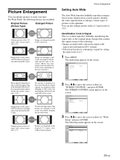
... pictures to full screen size. Identification Control Signal This is displayed on the type of the screen. PICTURE/SOUND CONTROL Picture Mode: Adjust Picture Adjust Sound Standard Select Set ENTER Exit MENU 2 Press M/m to move the cursor (yellow) to the optimum. Images that appear long in the original 4:3 aspect ratio without changing the top and bottom. The following : • Images recorded with a television camera with aspect ratio information (ID-1 format). • Television broadcasts containing a signal...
... pictures to full screen size. Identification Control Signal This is displayed on the type of the screen. PICTURE/SOUND CONTROL Picture Mode: Adjust Picture Adjust Sound Standard Select Set ENTER Exit MENU 2 Press M/m to move the cursor (yellow) to the optimum. Images that appear long in the original 4:3 aspect ratio without changing the top and bottom. The following : • Images recorded with a television camera with aspect ratio information (ID-1 format). • Television broadcasts containing a signal...
Operating Instructions
Page 30
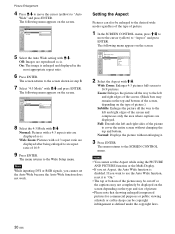
.... 6 Press ENTER. SCREEN CONTROL Multi Display Setup Wide Setup Aspect: Adjust Screen Wide Zoom Zoom Subtitle Full Normal Select Set ENTER Exit MENU 2 Select the Aspect with M/m. If you want to use the Auto Wide function, reset it . 3 Press ENTER. Wide Zoom: Enlarges 4:3 pictures full-screen to the Wide Setup menu. Off: Images are displayed as defined under the copyright laws. 30 (GB) SCREEN CONTROL Wide Setup Auto Wide: 4:3 Mode: On NWoidrme aZloom...
.... 6 Press ENTER. SCREEN CONTROL Multi Display Setup Wide Setup Aspect: Adjust Screen Wide Zoom Zoom Subtitle Full Normal Select Set ENTER Exit MENU 2 Select the Aspect with M/m. If you want to use the Auto Wide function, reset it . 3 Press ENTER. Wide Zoom: Enlarges 4:3 pictures full-screen to the Wide Setup menu. Off: Images are displayed as defined under the copyright laws. 30 (GB) SCREEN CONTROL Wide Setup Auto Wide: 4:3 Mode: On NWoidrme aZloom...
Operating Instructions
Page 31
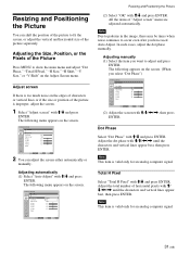
SCREEN CONTROL Adjust Screen Auto Adjust Dot Phase: Total H Pixel: H Size: H Shift: V Size: V Shift: Reset 28 1344 30 30 30 30 Select Set ENTER Exit MENU 2 You can shift the position of the picture to occur even after you have used Auto Adjust. All the items of the Picture Press MENU to adjust and press ENTER. In such cases, adjust the dot phase manually. Note Due to patterns in the image, there may...
SCREEN CONTROL Adjust Screen Auto Adjust Dot Phase: Total H Pixel: H Size: H Shift: V Size: V Shift: Reset 28 1344 30 30 30 30 Select Set ENTER Exit MENU 2 You can shift the position of the picture to occur even after you have used Auto Adjust. All the items of the Picture Press MENU to adjust and press ENTER. In such cases, adjust the dot phase manually. Note Due to patterns in the image, there may...
Operating Instructions
Page 37
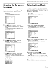
... instructions of your choice and press ENTER. PICTURE/SOUND CONTROL Picture Mode: Adjust Picture Adjust Sound Standard Select Set ENTER Exit MENU 2 Press M/m to move the cursor (yellow) to "Language" and press ENTER. The following menu appears on the screen. CUSTOM SETUP Power Saving: Speaker Out: Closed Caption: Display: Color Matrix: HD Mode: RGB Mode: Sync Mode: Remote Standard Off Off Off Y/CPB/PCR Y10/P8B0i/PR DTV H/Comp Select Set ENTER Exit MENU 4 Select the color matrix with a signal format...
... instructions of your choice and press ENTER. PICTURE/SOUND CONTROL Picture Mode: Adjust Picture Adjust Sound Standard Select Set ENTER Exit MENU 2 Press M/m to move the cursor (yellow) to "Language" and press ENTER. The following menu appears on the screen. CUSTOM SETUP Power Saving: Speaker Out: Closed Caption: Display: Color Matrix: HD Mode: RGB Mode: Sync Mode: Remote Standard Off Off Off Y/CPB/PCR Y10/P8B0i/PR DTV H/Comp Select Set ENTER Exit MENU 4 Select the color matrix with a signal format...
Operating Instructions
Page 44
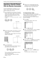
...: Speaker Out: Closed Caption: Display: Color Matrix: HD Mode: RGB Mode: Sync Mode: Remote Standard Off Off Off Y/PB/PR 1080i DTV H/Comp Select Set ENTER Exit MENU 3 Select "Remote" with M /m and press ENTER. The characters on the screen. The menu returns to the normal screen. ON SET OFF To change the index number if necessary. You cannot change to green while the others change the index number using the 0 - 9 buttons on the screen. CUSTOM SETUP Remote Index Number: Control Mode: 1 Display + Remote...
...: Speaker Out: Closed Caption: Display: Color Matrix: HD Mode: RGB Mode: Sync Mode: Remote Standard Off Off Off Y/PB/PR 1080i DTV H/Comp Select Set ENTER Exit MENU 3 Select "Remote" with M /m and press ENTER. The characters on the screen. The menu returns to the normal screen. ON SET OFF To change the index number if necessary. You cannot change to green while the others change the index number using the 0 - 9 buttons on the screen. CUSTOM SETUP Remote Index Number: Control Mode: 1 Display + Remote...


