Operating Instructions
Page 4
... of picture 41 (GB) Lowers the brightness level gradually 42 (GB) Setting an IP address and communication speed 42 (GB) Obtaining an IP address automatically (DHCP) .... 42 (GB) Setting an IP address manually (Manual 42 (GB) Setting a communication speed 43 (GB) Self-diagnosis Function 43 (GB) Operating a Specific Display With the Remote Commander 44 (GB...
... of picture 41 (GB) Lowers the brightness level gradually 42 (GB) Setting an IP address and communication speed 42 (GB) Obtaining an IP address automatically (DHCP) .... 42 (GB) Setting an IP address manually (Manual 42 (GB) Setting a communication speed 43 (GB) Self-diagnosis Function 43 (GB) Operating a Specific Display With the Remote Commander 44 (GB...
Operating Instructions
Page 12
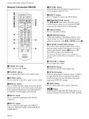
Press again to restore sound. 4DISPLAY button Press to display the input signal information and the picture mode on the display. 2STANDBY button Press to change the aspect ratio (Wide Mode). 9M/m/ Press again to the INPUT2 connectors. Location and Function of Parts and Controls Remote Commander RM-980 1 2 MUTING DISPLAY STBY ON 3 4 5 qf 6 qg 7 qh 8 qj 9 ENTER 123 0 456 789 qa 0 qk qs ON SET qd ql MONITOR RM-980 1POWER ON switch Press to power on the screen. Each press toggles between RGB and COMPONENT. 7PICTURE button Selects Picture mode. If this ...
Press again to restore sound. 4DISPLAY button Press to display the input signal information and the picture mode on the display. 2STANDBY button Press to change the aspect ratio (Wide Mode). 9M/m/ Press again to the INPUT2 connectors. Location and Function of Parts and Controls Remote Commander RM-980 1 2 MUTING DISPLAY STBY ON 3 4 5 qf 6 qg 7 qh 8 qj 9 ENTER 123 0 456 789 qa 0 qk qs ON SET qd ql MONITOR RM-980 1POWER ON switch Press to power on the screen. Each press toggles between RGB and COMPONENT. 7PICTURE button Selects Picture mode. If this ...
Operating Instructions
Page 20
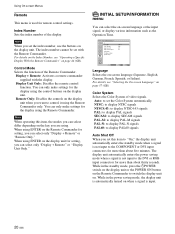
... of video signals. The index number cannot be set the Color System automatically. Display Unit Only: Disables the remote control function. For details, see "Operating a Specific Display With the Remote Commander" on the key you want to set with the display. While in the standby mode, press the 1POWER switch on...
... of video signals. The index number cannot be set the Color System automatically. Display Unit Only: Disables the remote control function. For details, see "Operating a Specific Display With the Remote Commander" on the key you want to set with the display. While in the standby mode, press the 1POWER switch on...

Operating Instructions
Page 39
... Time and press ENTER. When "Every day" is selected, you press ENTER with M/m and press ENTER. The screen returns to with the radio button set a specific time for the clock. The following menu appears on the screen. When "Day of week, change to the screen shown in the factory setting, so...
... Time and press ENTER. When "Every day" is selected, you press ENTER with M/m and press ENTER. The screen returns to with the radio button set a specific time for the clock. The following menu appears on the screen. When "Day of week, change to the screen shown in the factory setting, so...
Operating Instructions
Page 44
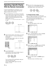
... completed, press the ID MODE OFF button. The main menu appears on page 44 (GB). Operating a Specific Display With the Remote Commander Operating a Specific Display With the Remote Commander Using the supplied Remote Commander, you can operate a specific display without affecting other displays, as well.) 44 (GB) Select Set ENTER Exit MENU 2 Select...
... completed, press the ID MODE OFF button. The main menu appears on page 44 (GB). Operating a Specific Display With the Remote Commander Operating a Specific Display With the Remote Commander Using the supplied Remote Commander, you can operate a specific display without affecting other displays, as well.) 44 (GB) Select Set ENTER Exit MENU 2 Select...
Operating Instructions
Page 45
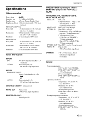
... OUT Pinjack (×2) 500 mVrms, high impedance REMOTE (RS-232C) D-sub 9-pin (×1) Specifications VIDEO/S VIDEO input/output adaptor BKM-FW10 (only for the FWD-42LX1/ 32LX1) VIDEO (NTSC, PAL, SECAM, NTSC4.43, PAL60, PAL-M, PAL-N)1) VIDEO IN...Panel system AC-type Plasma Display Panel Display resolution 1366 dots (horizontal) × 768 lines (vertical) FWD-42PV1/42PV1A: Pixel pitch 1.08 (horizontal) × 1.08 (vertical) mm (1⁄16 × 1⁄16 inches) Picture size 920 (horizontal) × 518 (vertical) mm (36 1⁄4 × 20 1⁄2 inches) Panel size 42...
... OUT Pinjack (×2) 500 mVrms, high impedance REMOTE (RS-232C) D-sub 9-pin (×1) Specifications VIDEO/S VIDEO input/output adaptor BKM-FW10 (only for the FWD-42LX1/ 32LX1) VIDEO (NTSC, PAL, SECAM, NTSC4.43, PAL60, PAL-M, PAL-N)1) VIDEO IN...Panel system AC-type Plasma Display Panel Display resolution 1366 dots (horizontal) × 768 lines (vertical) FWD-42PV1/42PV1A: Pixel pitch 1.08 (horizontal) × 1.08 (vertical) mm (1⁄16 × 1⁄16 inches) Picture size 920 (horizontal) × 518 (vertical) mm (36 1⁄4 × 20 1⁄2 inches) Panel size 42...
Operating Instructions
Page 46
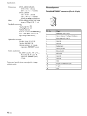
Specifications Dimensions FWD-42PV1/42PV1A: 1033 × 631 × 121 mm (40 3⁄4 × 24 7⁄8 × 4 7⁄8 inches) FWD-42PV1P: 631 × 1033 × 121 mm (24 7⁄8 × 40 3⁄4 × 4 7⁄8 inches) (w/h/d, excluding projections) Mass FWD-42PV1/42PV1P/42PV1A: Approx. 29 kg (63 lb..., BKM-FW series Safety regulations UL1950, CSA No. 950 (c-UL), FCC Class B, IC Class B, EN60 950 (NEMKO), CE, C-Tick Design and specifications are subject to change without notice. Pin assignment RGB/COMPONENT connector (D-sub 15-pin) Pin No. 1 2 3 4 5 6 7 8 9 10...
Specifications Dimensions FWD-42PV1/42PV1A: 1033 × 631 × 121 mm (40 3⁄4 × 24 7⁄8 × 4 7⁄8 inches) FWD-42PV1P: 631 × 1033 × 121 mm (24 7⁄8 × 40 3⁄4 × 4 7⁄8 inches) (w/h/d, excluding projections) Mass FWD-42PV1/42PV1P/42PV1A: Approx. 29 kg (63 lb..., BKM-FW series Safety regulations UL1950, CSA No. 950 (c-UL), FCC Class B, IC Class B, EN60 950 (NEMKO), CE, C-Tick Design and specifications are subject to change without notice. Pin assignment RGB/COMPONENT connector (D-sub 15-pin) Pin No. 1 2 3 4 5 6 7 8 9 10...