Operating Instructions
Page 12
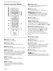
If this displayed information is left undisturbed for five minutes, it will disappear automatically. 5INPUT1 button Press to select the signal input to the INPUT1 connectors. 6INPUT2 button Press to select the signal input to mute the sound. Each press toggles between Vivid, Standard, and User 1 to 3. 8ASPECT button Press to change the display to the standby mode. 3MUTING button Press to the INPUT2 connectors. Location and Function of Parts and Controls Remote Commander RM-980 1 2 MUTING DISPLAY STBY ON 3 4 5 qf 6 qg 7 qh 8 qj 9 ENTER 123 0 456 789 qa 0 qk qs ON ...
If this displayed information is left undisturbed for five minutes, it will disappear automatically. 5INPUT1 button Press to select the signal input to the INPUT1 connectors. 6INPUT2 button Press to select the signal input to mute the sound. Each press toggles between Vivid, Standard, and User 1 to 3. 8ASPECT button Press to change the display to the standby mode. 3MUTING button Press to the INPUT2 connectors. Location and Function of Parts and Controls Remote Commander RM-980 1 2 MUTING DISPLAY STBY ON 3 4 5 qf 6 qg 7 qh 8 qj 9 ENTER 123 0 456 789 qa 0 qk qs ON ...
Operating Instructions
Page 19
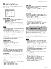
... of RGB/COMPONENT connector. Input horizontal/vertical synchronization signals through the 13 or 14 pin connectors, or input Sync On Green signals through the option boards. • This unit does not support the three value sync format of the composite synchronous signal, the image may lose the energy saving effects if...
... of RGB/COMPONENT connector. Input horizontal/vertical synchronization signals through the 13 or 14 pin connectors, or input Sync On Green signals through the option boards. • This unit does not support the three value sync format of the composite synchronous signal, the image may lose the energy saving effects if...
