Operating Instructions
Page 6
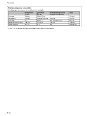
Precautions Warning on power connection Use the proper power cord for your local power supply. Japan VM1296 VM1313 HVCTF 10A/125V DENAN-HO 6 (GB) Plug type Female end Cord type Minimum cord set rating Safety approval United States, Canada VM0233 VM0089 SVT 10A/125V UL/CSA Continental Europe United Kingdom, Ireland, Australia, New Zealand COX-07 636 -a) COX-02 VM0310B VM0303B H05VV-F CEE (13) 53rd (O.C) 10A/250V 10A/250V VDE VDE a) Note: Use an appropriate rating plug which complies with local regulations.
Precautions Warning on power connection Use the proper power cord for your local power supply. Japan VM1296 VM1313 HVCTF 10A/125V DENAN-HO 6 (GB) Plug type Female end Cord type Minimum cord set rating Safety approval United States, Canada VM0233 VM0089 SVT 10A/125V UL/CSA Continental Europe United Kingdom, Ireland, Australia, New Zealand COX-07 636 -a) COX-02 VM0310B VM0303B H05VV-F CEE (13) 53rd (O.C) 10A/250V 10A/250V VDE VDE a) Note: Use an appropriate rating plug which complies with local regulations.
Operating Instructions
Page 7
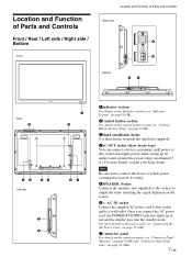
...the control button section, see "Connector Panel (Bottom)" on page 9 (GB) and "Connector Panel (Left side)" on the screen. 6- For more details on the power cord, see "Connecting the AC Power Cord" on page 15 (GB). 7Connector panel For details on the connector panel, see "Control Button Section (Top.... Once you connect the AC power cord, the POWER/STANDBY indicator lights up an audio/visual system (the power rating: maximum 0.5 A). For more details, consult your Sony dealer. AC IN socket Connect the supplied AC power cord to this socket and supply power when setting up in red and...
...the control button section, see "Connector Panel (Bottom)" on page 9 (GB) and "Connector Panel (Left side)" on the screen. 6- For more details on the power cord, see "Connecting the AC Power Cord" on page 15 (GB). 7Connector panel For details on the connector panel, see "Control Button Section (Top.... Once you connect the AC power cord, the POWER/STANDBY indicator lights up an audio/visual system (the power rating: maximum 0.5 A). For more details, consult your Sony dealer. AC IN socket Connect the supplied AC power cord to this socket and supply power when setting up in red and...
Operating Instructions
Page 11
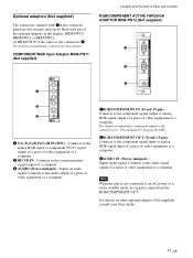
... your Sony dealers. For details on page 46 (GB). 2RGB/COMPONENT OUT (D-sub 15-pin) : Connects to the audio signal output of a piece of video equipment or a computer. AUDIO VD 1RGB/COMPONENT IN (D-sub 15-pin) : Connects to an AC power or is in the display; Connects to the component ...or BKM-FW12. (A BKM-FW10 is the same as the connectors 7.) For details on installation, consult your Sony dealer. 11 (GB) Optional adaptors (Not supplied) The connectors marked with 7on the connector panel are slot-in types and can be fitted with any of the optional adaptors in the standby mode, no...
... your Sony dealers. For details on page 46 (GB). 2RGB/COMPONENT OUT (D-sub 15-pin) : Connects to the audio signal output of a piece of video equipment or a computer. AUDIO VD 1RGB/COMPONENT IN (D-sub 15-pin) : Connects to an AC power or is in the display; Connects to the component ...or BKM-FW12. (A BKM-FW10 is the same as the connectors 7.) For details on installation, consult your Sony dealer. 11 (GB) Optional adaptors (Not supplied) The connectors marked with 7on the connector panel are slot-in types and can be fitted with any of the optional adaptors in the standby mode, no...

Operating Instructions
Page 14
...qualified Sony personnel for proper ventilation. • The ambient temperature must be 0 °C to +35 °C (32 °F to 95 °F). • When installing the display horizontally, use the display, make sure there is powered on , a certain amount of heat builds up to the FWD-...rear of hardware such as a stand. • Regarding the installation of the unit when it has entered standby mode. When using the stand (not supplied) Front 20 (7 7/8) 10 10 (4) (4) When mounting the display horizontally Front 25 (9 7/8) 10 10 (4) (4) Side 25 (9 7/8) 5 (2) Units: ...
...qualified Sony personnel for proper ventilation. • The ambient temperature must be 0 °C to +35 °C (32 °F to 95 °F). • When installing the display horizontally, use the display, make sure there is powered on , a certain amount of heat builds up to the FWD-...rear of hardware such as a stand. • Regarding the installation of the unit when it has entered standby mode. When using the stand (not supplied) Front 20 (7 7/8) 10 10 (4) (4) When mounting the display horizontally Front 25 (9 7/8) 10 10 (4) (4) Side 25 (9 7/8) 5 (2) Units: ...
Operating Instructions
Page 15
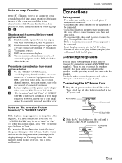
...noise. • To disconnect the cable, pull it connects to "Using the cable holders" on page 16 (GB). Connecting the AC Power Cord 1 Plug the AC power cord into the AC IN socket. • Use one of connected equipment. It is not a malfunction. Situations which can enjoy viewing... set to the user manual of the two AC plug holders (supplied) that came with 4:3 video source (conventional TV broadcast) 3 Video game sources 4 DVD on-screen menu displays 5 On-screen menus, channel numbers, etc., of the Plasma Display Panel. Notes on Image Retention If the 1- 5images (below) are ...
...noise. • To disconnect the cable, pull it connects to "Using the cable holders" on page 16 (GB). Connecting the AC Power Cord 1 Plug the AC power cord into the AC IN socket. • Use one of connected equipment. It is not a malfunction. Situations which can enjoy viewing... set to the user manual of the two AC plug holders (supplied) that came with 4:3 video source (conventional TV broadcast) 3 Video game sources 4 DVD on-screen menu displays 5 On-screen menus, channel numbers, etc., of the Plasma Display Panel. Notes on Image Retention If the 1- 5images (below) are ...
Operating Instructions
Page 19
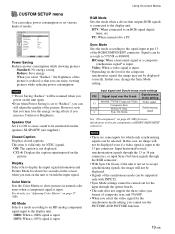
...can be supported only with INPUT2. • Sync Mode settings cannot be emmited from the speakers SS-SP42FW (not supplied.) Closed Caption Displays closed captions. Notes • "Power Saving: Reduce" will be resumed when you cannot use the PICTURE AND PICTURE function. 19 (GB) Speaker Out Set... pin assignments of the composite synchronous signal, the image may lose the energy saving effects if you can enjoy viewing pictures while reducing power consumption. PIN 13 13/14 2 Input signal and Synchronous mode settings Signal input over the D-sub Synchronous mode setting 480/60I, ...
...can be supported only with INPUT2. • Sync Mode settings cannot be emmited from the speakers SS-SP42FW (not supplied.) Closed Caption Displays closed captions. Notes • "Power Saving: Reduce" will be resumed when you cannot use the PICTURE AND PICTURE function. 19 (GB) Speaker Out Set... pin assignments of the composite synchronous signal, the image may lose the energy saving effects if you can enjoy viewing pictures while reducing power consumption. PIN 13 13/14 2 Input signal and Synchronous mode settings Signal input over the D-sub Synchronous mode setting 480/60I, ...
Operating Instructions
Page 20
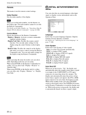
..., the modes you set with the display. While in the standby mode, press the 1POWER switch on the display unit or the POWER ON button on the Remote Commander to the DVI or RGB input connectors for more than about thirty seconds. Display Unit Only: Disables... display unit is automatically turned on when a signal is input. 20 (GB) Display + Remote: Activates a remote commander supplied with the Remote Commander. The display unit automatically enters the power saving mode when a signal is not input to switch the display unit on. For details, see "Operating a Specific Display...
..., the modes you set with the display. While in the standby mode, press the 1POWER switch on the display unit or the POWER ON button on the Remote Commander to the DVI or RGB input connectors for more than about thirty seconds. Display Unit Only: Disables... display unit is automatically turned on when a signal is input. 20 (GB) Display + Remote: Activates a remote commander supplied with the Remote Commander. The display unit automatically enters the power saving mode when a signal is not input to switch the display unit on. For details, see "Operating a Specific Display...
Operating Instructions
Page 44
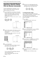
Operating a Specific Display With the Remote Commander Operating a Specific Display With the Remote Commander Using the supplied Remote Commander, you want to operate using the Remote Commander. 1 Press MENU. When you change the index number You can operate the specified ...the screen. CUSTOM SETUP Remote Index Number: Control Mode: 1 Display + Remote Select Set ENTER Exit MENU 4 Select the index number with green characters only. (Power ON/STANDBY apply to the other displays installed at the same time. 1 Press ID MODE ON on the control button section of each display. 123...
Operating a Specific Display With the Remote Commander Operating a Specific Display With the Remote Commander Using the supplied Remote Commander, you want to operate using the Remote Commander. 1 Press MENU. When you change the index number You can operate the specified ...the screen. CUSTOM SETUP Remote Index Number: Control Mode: 1 Display + Remote Select Set ENTER Exit MENU 4 Select the index number with green characters only. (Power ON/STANDBY apply to the other displays installed at the same time. 1 Press ID MODE ON on the control button section of each display. 123...
Operating Instructions
Page 46
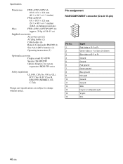
...: 631 × 1033 × 121 mm (24 7⁄8 × 40 3⁄4 × 4 7⁄8 inches) (w/h/d, excluding projections) Mass FWD-42PV1/42PV1P/42PV1A: Approx. 29 kg (63 lb 15 oz) Supplied accessories AC power cord (1) AC plug holder (2) Cable holder (6) Remote Commander RM-980 (1) Size AAA (R03) batteries (2) Operating instructions (1) Optional accessories Display stand SU-42FW...
...: 631 × 1033 × 121 mm (24 7⁄8 × 40 3⁄4 × 4 7⁄8 inches) (w/h/d, excluding projections) Mass FWD-42PV1/42PV1P/42PV1A: Approx. 29 kg (63 lb 15 oz) Supplied accessories AC power cord (1) AC plug holder (2) Cable holder (6) Remote Commander RM-980 (1) Size AAA (R03) batteries (2) Operating instructions (1) Optional accessories Display stand SU-42FW...


